Candela Technologies Logo
Network Testing and Emulation Solutions

LANforge WiFi Dual Virtual AP Setup with Limited Stations

Goal: Configure Two virtual APs with a maximum of ten stations each.

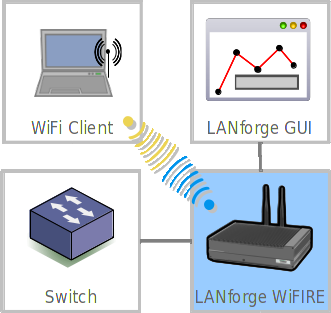
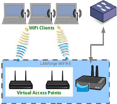
Requires at least a two-radio WiFIRE system such as a CT522, CT523 or CT525. This cookbook provides a basic setup to put a Virtual AP on each of two radios. Both APs are operating on separate channels but share the same SSID. We layout a basic constellation of APs in WPA2 mode that quickly fill up and force a station to search multiple channels for a free AP. This is the condition for issuing a Code 17 association refusal. This is not a roaming setup (Wireless Roaming/HS2.0 or 802.11r) because it is not configuring enterprise authentication or roaming specifications.
 
  1. Configure two radios to serve the role of Virtual APs. screenshot
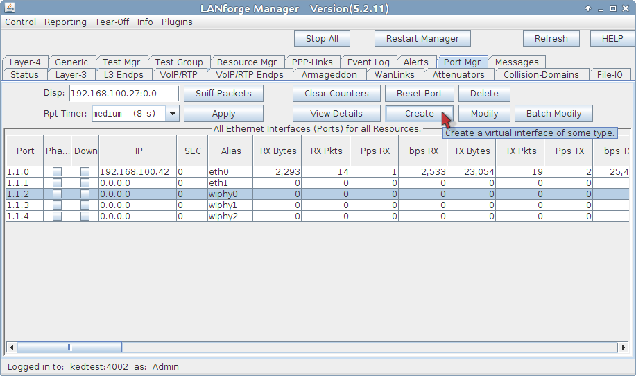
    1. Start at the Ports tab. We will configure our second ethernet port as the upstream port for the virtual APs. screenshot
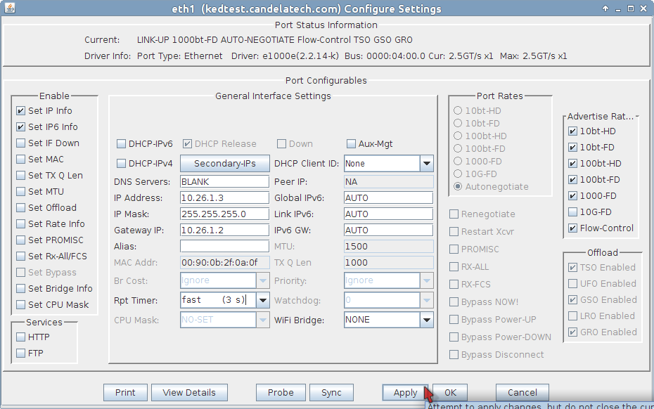
      1. Highlight port eth1 and click Modify
      2. Set the IP address to 10.26.1.3
      3. and the netmask to 255.255.255.0
      4. with a gateway address of the 10.26.1.2. (This gateway address matches the eth1 port of a separate system that hosts stations.
      5. Click OK
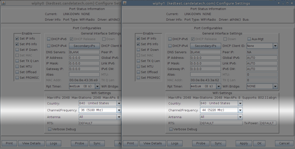
    2. In the Ports tab, select radios wiphy0, wiphy1 and click Modify. You will get two modify windows that you will want to place side by side. screenshot
      1. Set the channel of wiphy0 to 36
      2. and the channel of wiphy1 to 44
      3. Click OK in both windows.
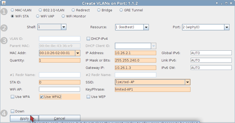
    3. Time to create the first virtual AP. In the Ports tab, select wiphy0 and click Create. screenshot
      1. Select WiFi VAP
      2. Enter a MAC address: 00:10:26:02:00:01
      3. Quantity is 1
      4. IP of 10.26.2.1
      5. Let's use a typical subnet mask: 255.255.255.0
      6. Gateway IP will be from eth1: 10.26.1.3
      7. We will setup WPA2 with the SSID limited-AP and Key/Phrase limited-AP1
      8. Click Apply to commit.
      9. Click Cancel to close the window.
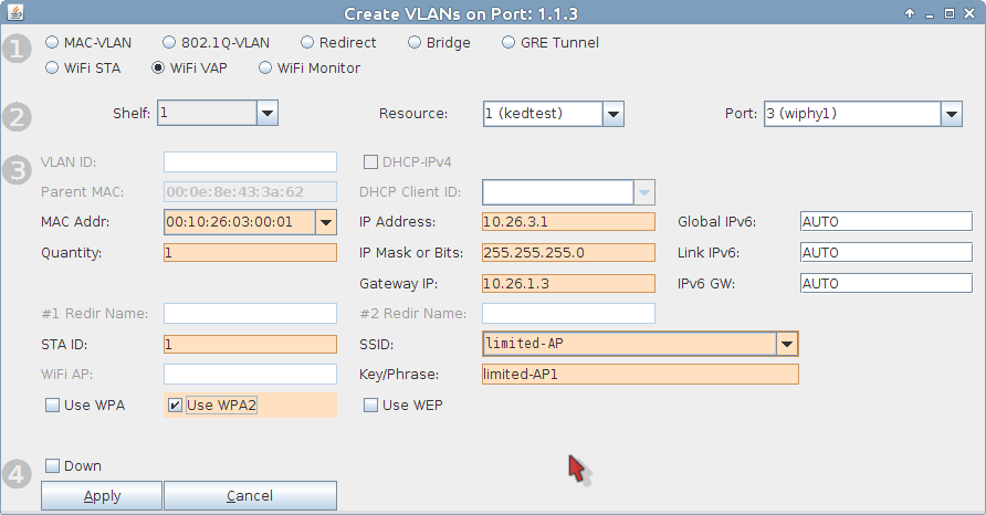
    4. Now craft a second virtual AP. In the Ports tab, select wiphy1 and click Create. screenshot
      1. Select WiFi VAP
      2. Enter a MAC address: 00:10:26:03:00:01
      3. Quantity is 1
      4. IP of 10.26.3.1
      5. And a typical subnet mask of 255.255.255.0
      6. Gateway IP will be from eth1: 10.26.1.3
      7. We will setup WPA2 with the SSID limited-AP and Key/Phrase limited-AP1
      8. Click Apply to commit.
      9. Click Cancel to close the window.
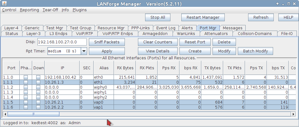
    5. We now have two virtual access points on two radios on separate channels. Each is on their own subnet. Now we limit the number of stations that can connect to them. screenshot
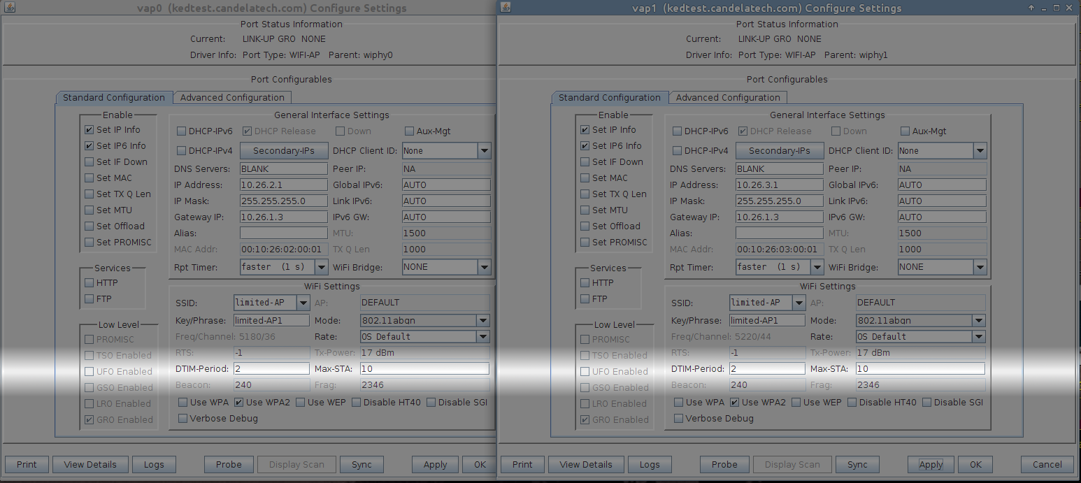
    6. In the Ports tab, hightlight endpoints vap0 and vap1 and click Modify screenshot
      1. At the bottom of the Port Configure Settings window for vap0, change Max-STA to 10
      2. Click OK
      3. Repeat this for vap1
  2. We now have two virtual access points that can both accept a small number of stations. We put them on different subnets because configuring DHCP on each VAP is simpler than adding a bridge device..
  3. Let's proceed to configuring DHCP for the 10.26.2.0/24 and 10.26.3.0/24 networks.
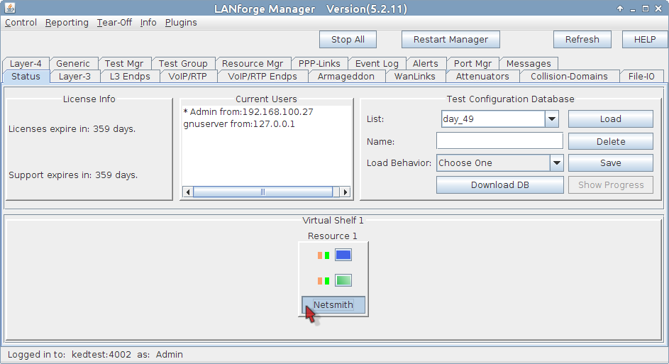
  4. In the Status tab, click on Netsmith screenshot
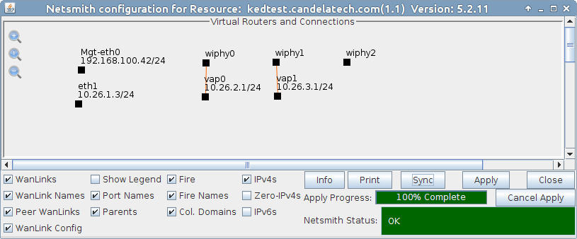
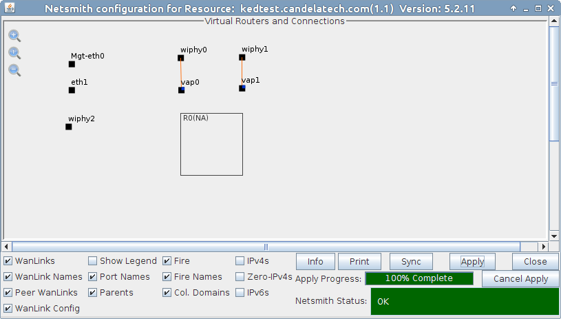
    1. Arrange your ports in the Netsmith windows and click Apply screenshot
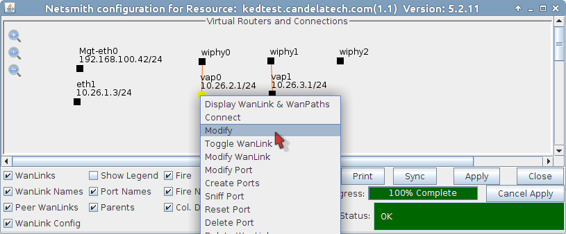
    2. Select vap0 and right click, choose Modify screenshot
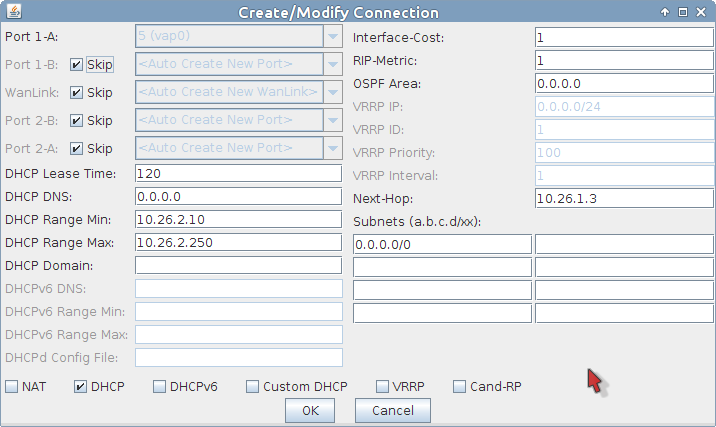
    3. Enable the DHCP pool and the Next-hop for the port screenshot
      1. Select DHCP
      2. Set DHCP Lease Time to 120
      3. Set DHCP Range Min to 10.26.2.10
      4. Set DHCP Range Max to 10.26.2.250
      5. Set Next-Hop to 10.26.1.3
      6. Add Subnet 0.0.0.0/0
      7. Click OK
    4. Click Apply in the Netsmith window to commit the changes to LANforge. If you do not, these changes will disappear.
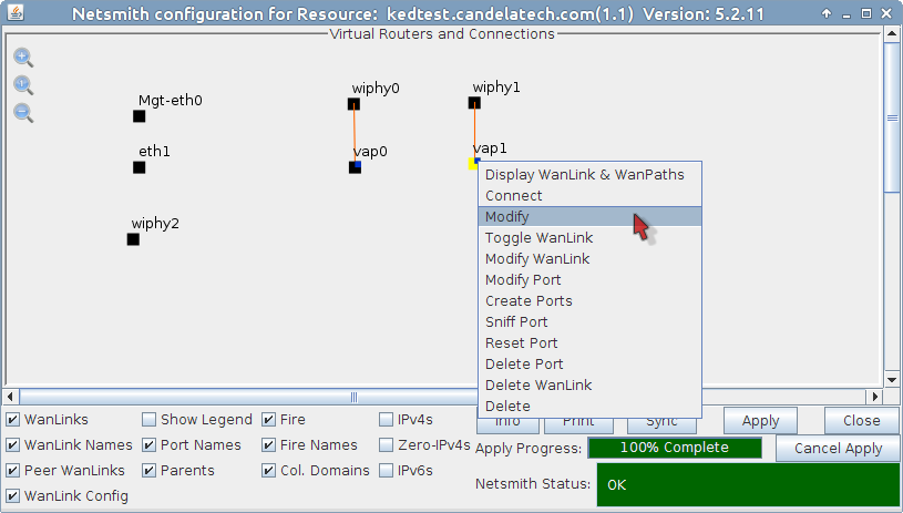
    5. In the Netsmith window, select vap1 and right click, choose Modify screenshot
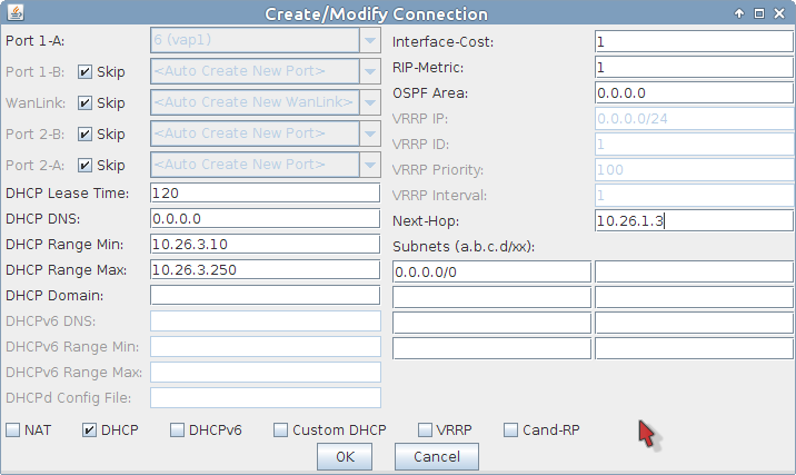
    6. Configure the DHCP pool and the Next-hop for vap1 screenshot
      1. Select DHCP
      2. Set DHCP Lease Time to 120
      3. Set DHCP Range Min to 10.26.3.10
      4. Set DHCP Range Max to 10.26.3.250
      5. Set Next-Hop to 10.26.1.3
      6. Add Subnet 0.0.0.0/0
      7. Click OK
    7. Click Apply in the Netsmith window to commit the changes to LANforge.
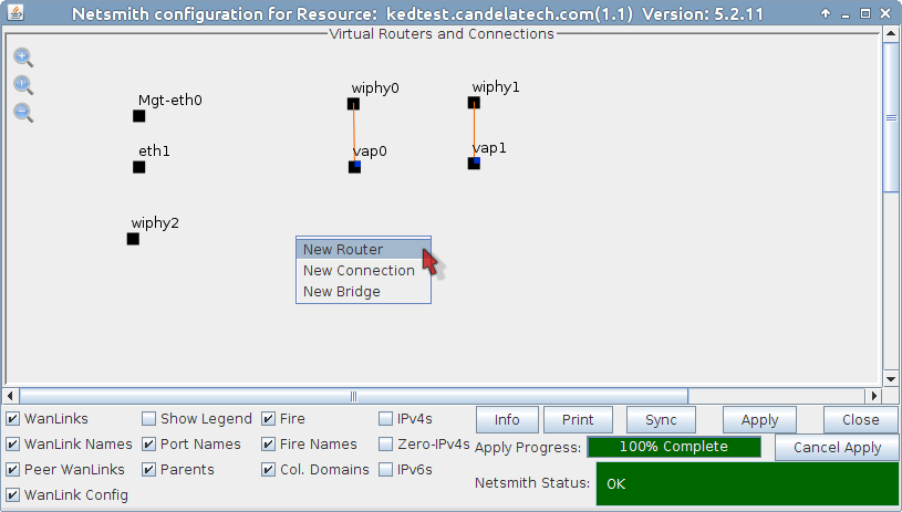
    8. We will create a virtual router to allow upstream traffic to reach the virtual access points: screenshot
      1. Right click in the Netsmith window and select New Router
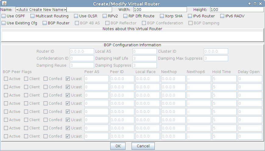
      2. You will see the Create/Modify Virtual Router window. We can use a default configuration. screenshot
      3. Click OK to save a default router screenshot
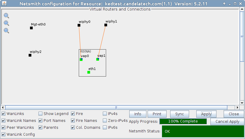
      4. Drag the endpoints vap0, vap1 and eth1 into the virtual router, then click Apply in the Netsmith window. screenshot
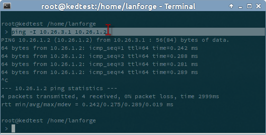
      5. We can verify outbound traffic using the following ping command. Open a terminal on the LANforge system and run ping -I 10.26.3.1 10.26.1.2 screenshot

Candela  Technologies, 2417 Main Street, Suite 201, Ferndale, WA 98248, USA
www.candelatech.com | sales@candelatech.com | +1.360.380.1618
Facebook | LinkedIn | Blog