Candela Technologies Logo
Network Testing and Emulation Solutions

Testing AP with automated TR-398 scenario

Goal: Setup and run a TR-398 test for an AP using a 6-radio version of the LANforge CT523c or similar system in order to test how well the AP can handle the various test cases specified in the TR-398 test document.

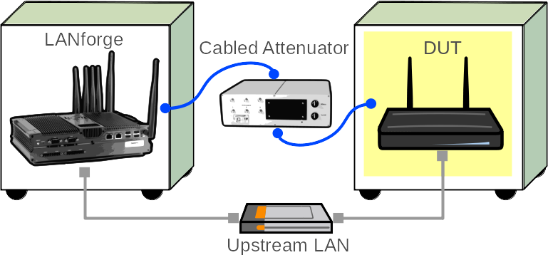
In this test scenario, the LANforge CT523c is used to emulate different station and AP scenarios and generate and receive traffic through an AP. This example assumes you have some experience with Chamber View, and that you have an appropriate LANforge system, programmable attenuators like the CT714 and two isolation chambers like the CT820a and CT840a. The AP should be in the chamber with the 2D turntable, the LANforge system is in the other chamber, and the attenuators are cabled between them. This feature requires LANforge version 5.4.1 or higher and the LANforge TR-398 automation software license.

 
  1. Configure Chamber View for TR-398 and Similar Tests.
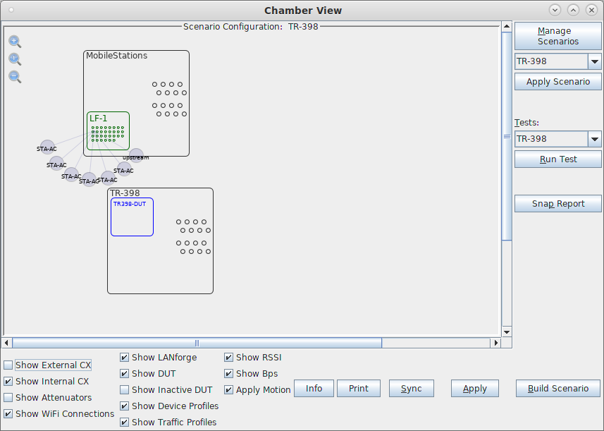
    1. Open Chamber View by clicking on the 'Chamber View' button in the LANforge-GUI. If you have an appropriate scenario already created, then skip to the next section, otherwise you will need to build a scenario that matches your system. You can right-click in Chamber View to create various objects. In this example, the 'Mobilestations' chamber holds the LANforge, and the TR-398 chamber holds the Device Under Test. Your configuration should look like this when these steps are complete. screenshot
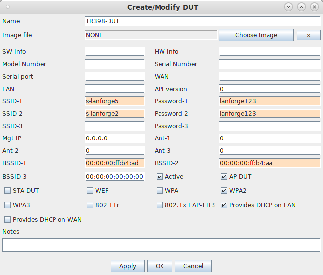
    2. Create a Device Under Test (DUT) Profile that matches your AP. The BSSID is important to configured so that LANforge knows when it is connected to the correct AP. screenshot
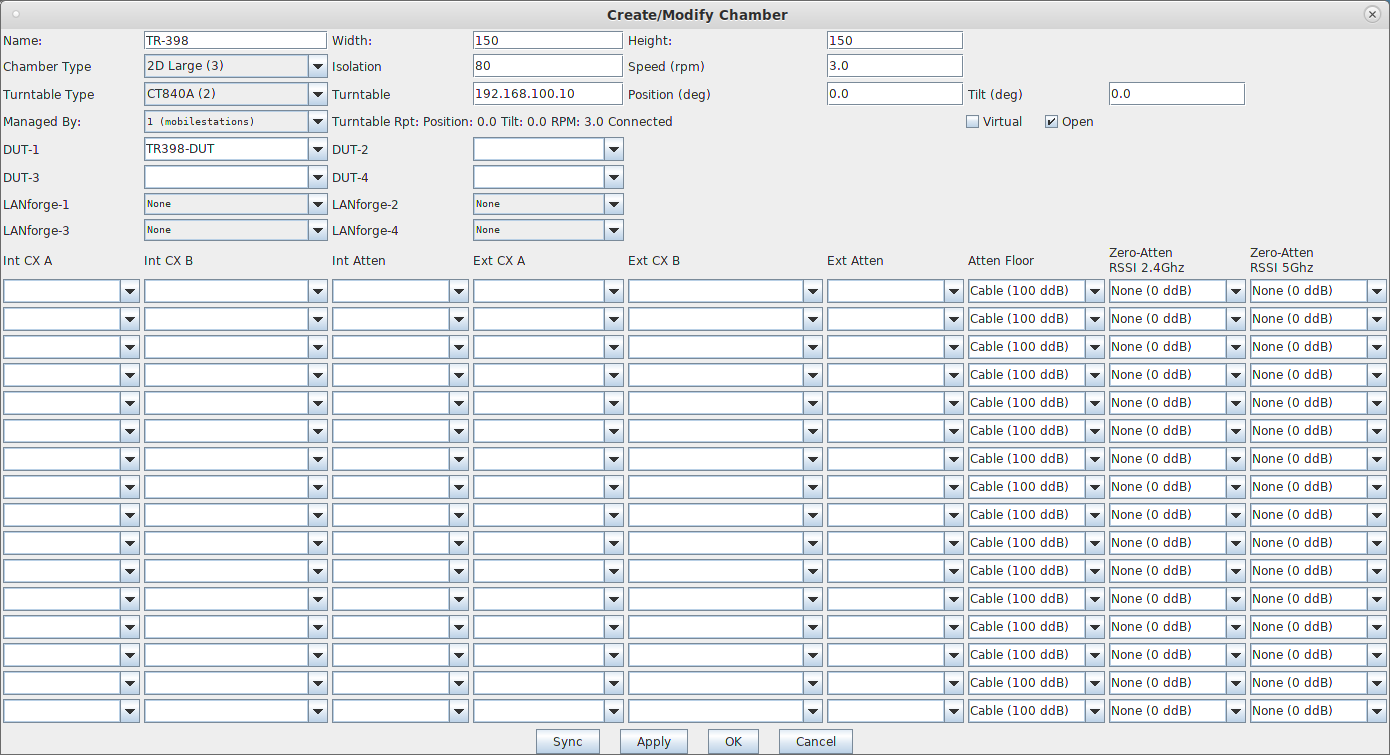
    3. Create a chamber object to hold the DUT, and add the DUT to that chamber. If you have no chambers, you can create a fake chamber, but your test will not be isolated and may not function as desired. The turntable configuration is different for different models of chambers, this example (bare IP address) is for the CT840a chamber. screenshot
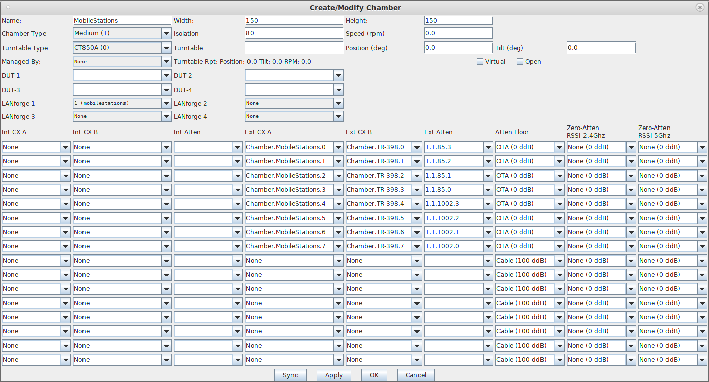
    4. Create a chamber object to hold the LANforge system, and add the LANforge to it. Add connections from this chamber to the DUT chamber, specifying the proper Attenuator modules. Please note we use the 'OTA' attenuation floor since we have OTA connection between DUT and antennas inside the DUT chamber. Please view our other cookbook on setting up attenuator connections in LANforge. screenshot
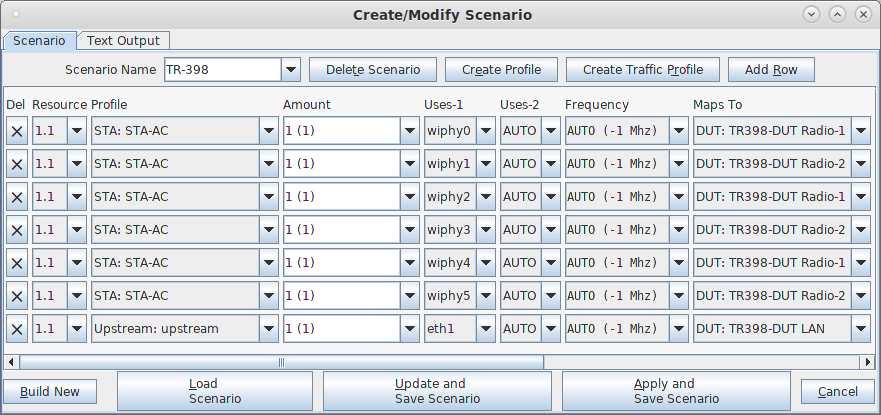
    5. Configure a Chamber View Scenario and add the STA profile (mapped to desired wiphyX radio and DUT). Add an upstream profile mapped to DUT LAN side (or possibly WAN side if that is more appropriate for your DUT). screenshot
  2. Use Chamber View for TR-398 test.
    1. Open Chamber View by clicking on the 'Chamber View' button in the LANforge-GUI. Load appropriate scenario. Apply the Scenario, then Build the scenario. screenshot
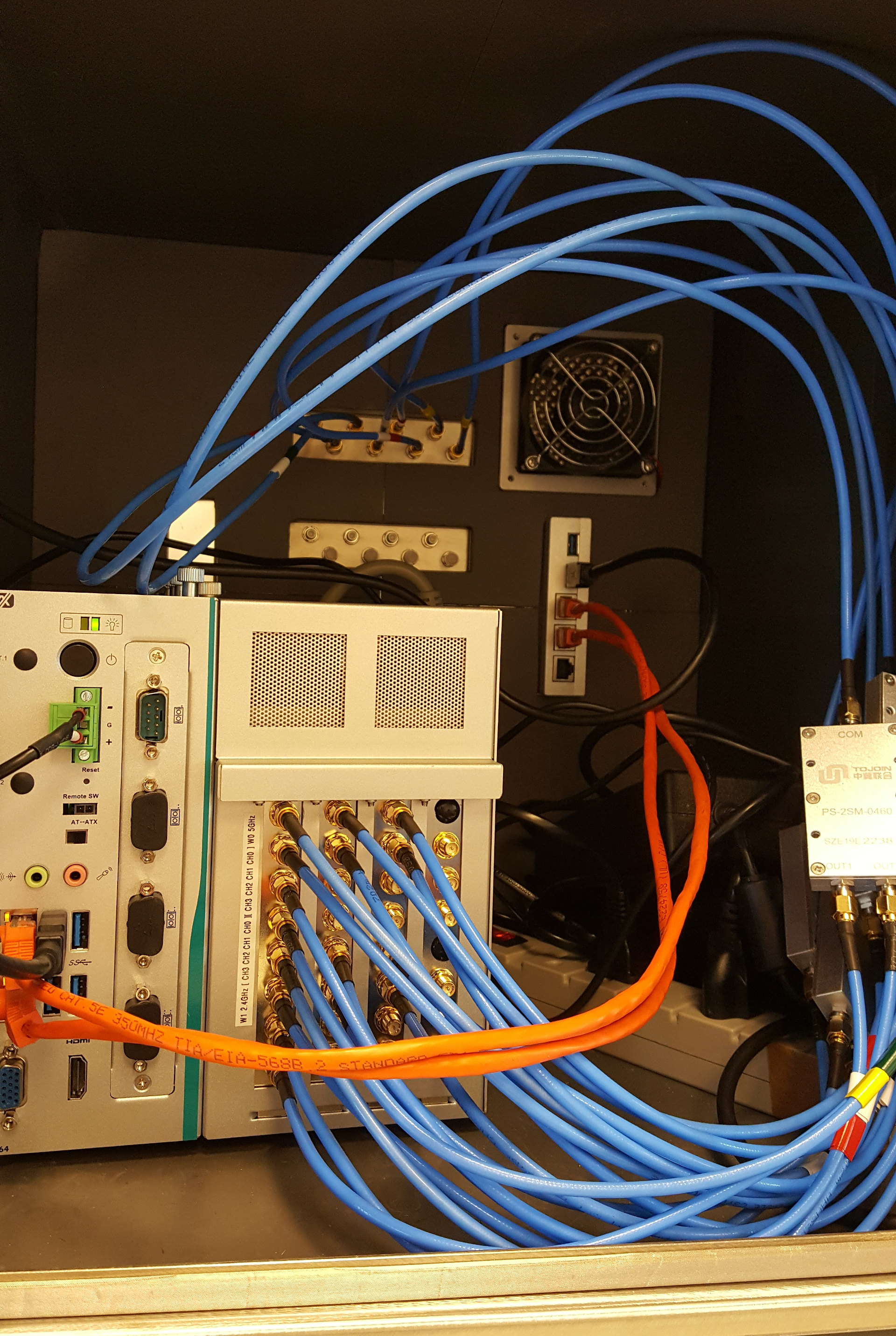
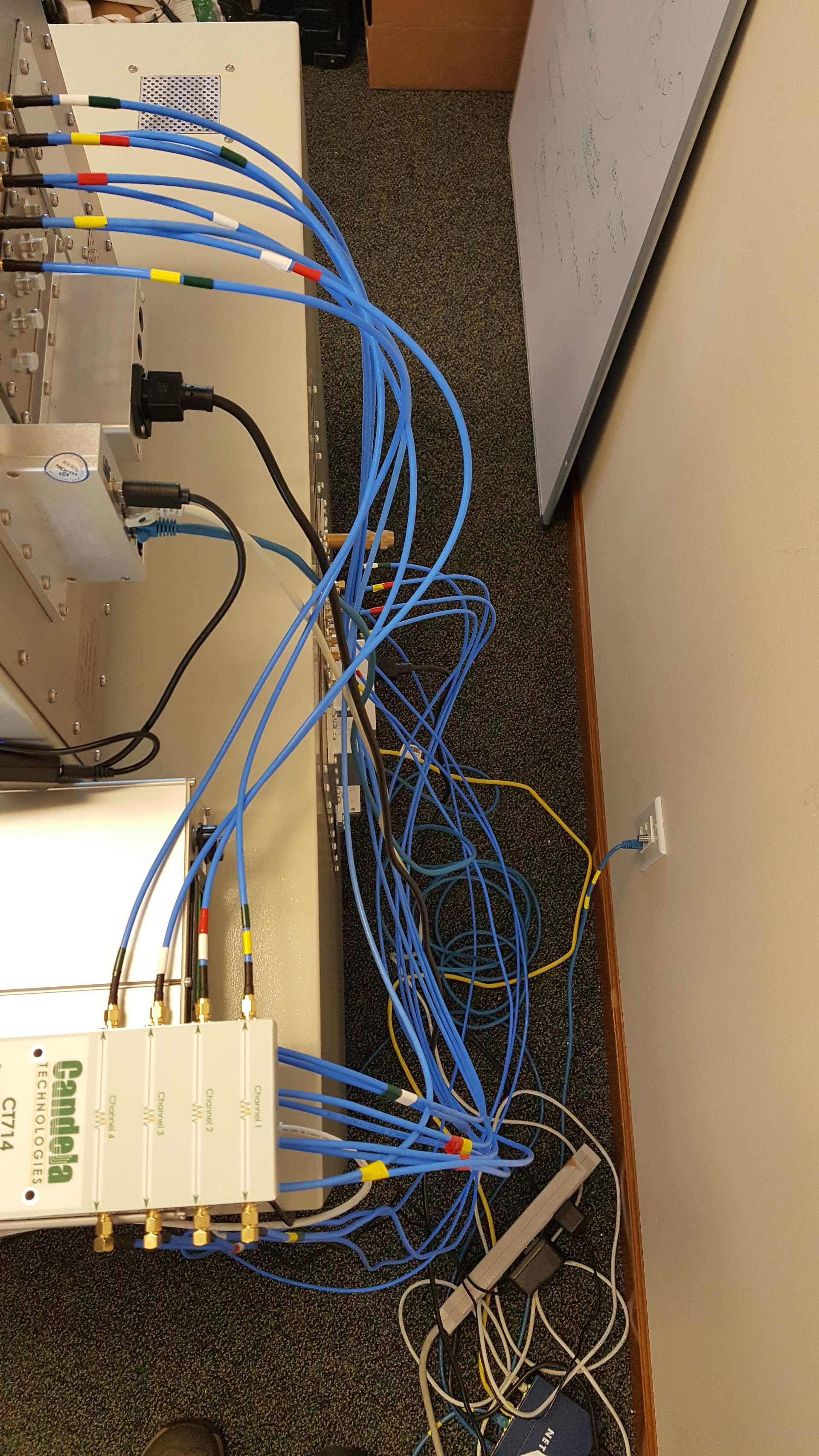
    2. To help make the cable routing easier to understand, you may wish to color-code the cables with tape or other similar markings.. Inside of the LANforge chamber: screenshot
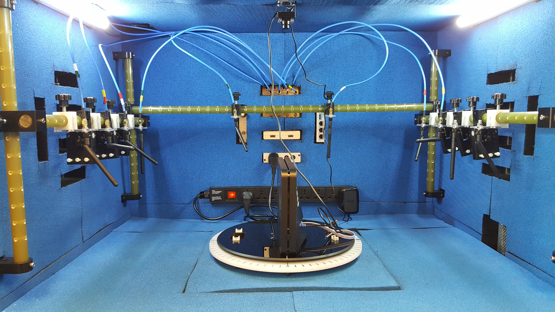
    3. Inside of the DUT chamber: screenshot
    4. Outside, back view: screenshot
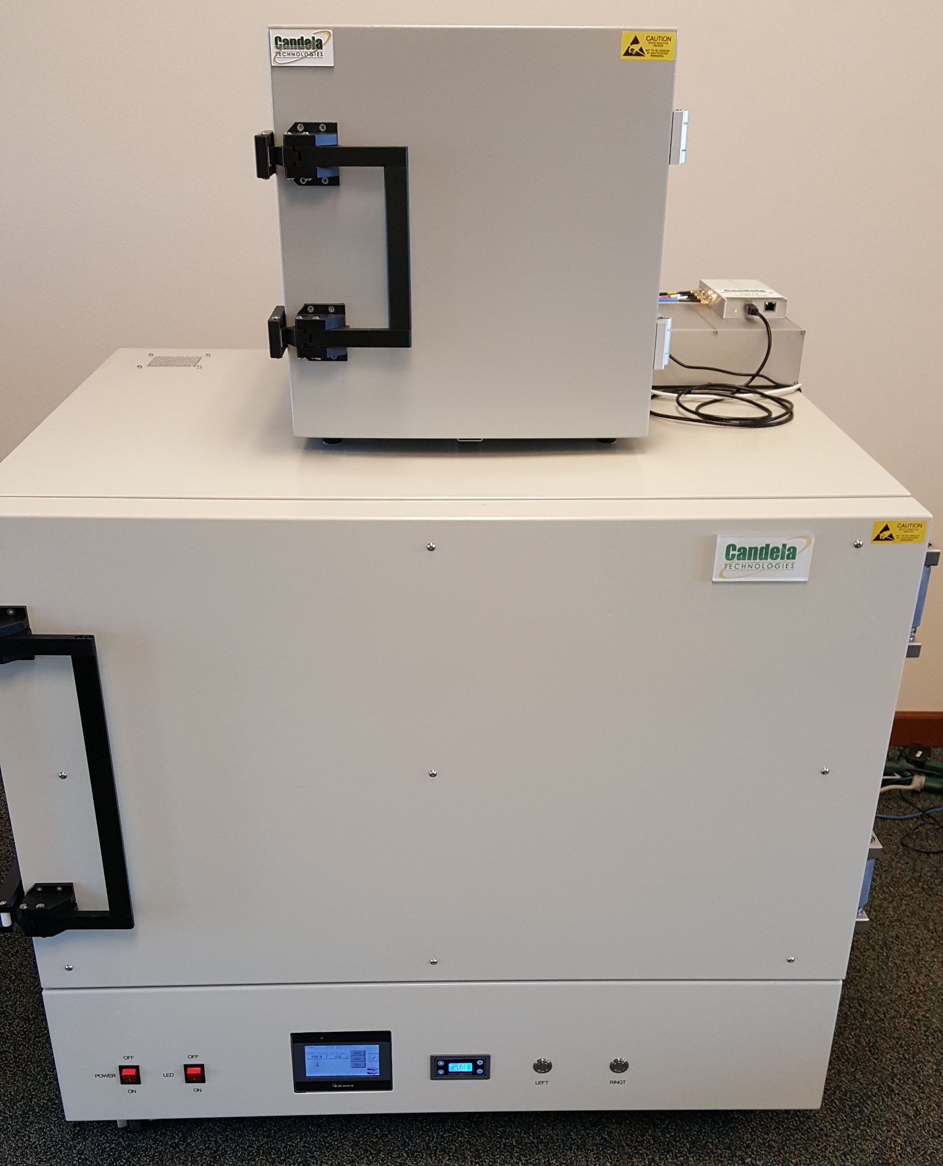
    5. Front view, all closed up and ready to test: screenshot
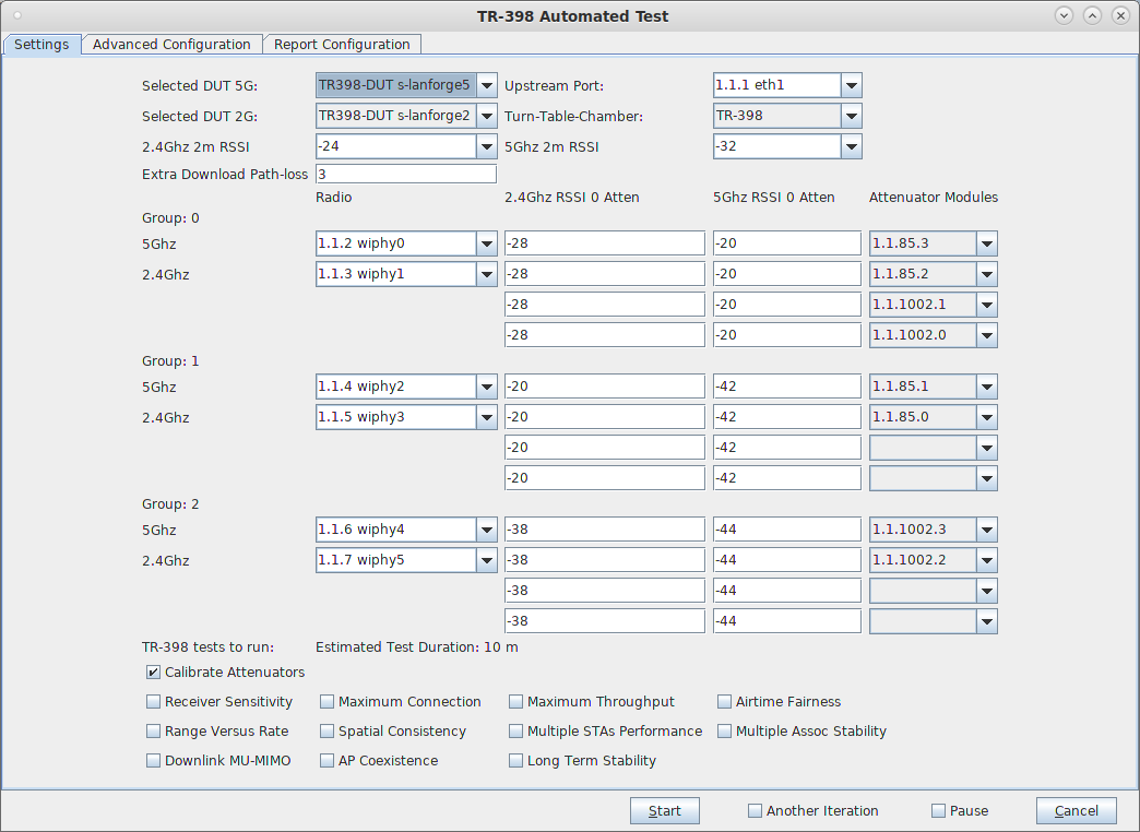
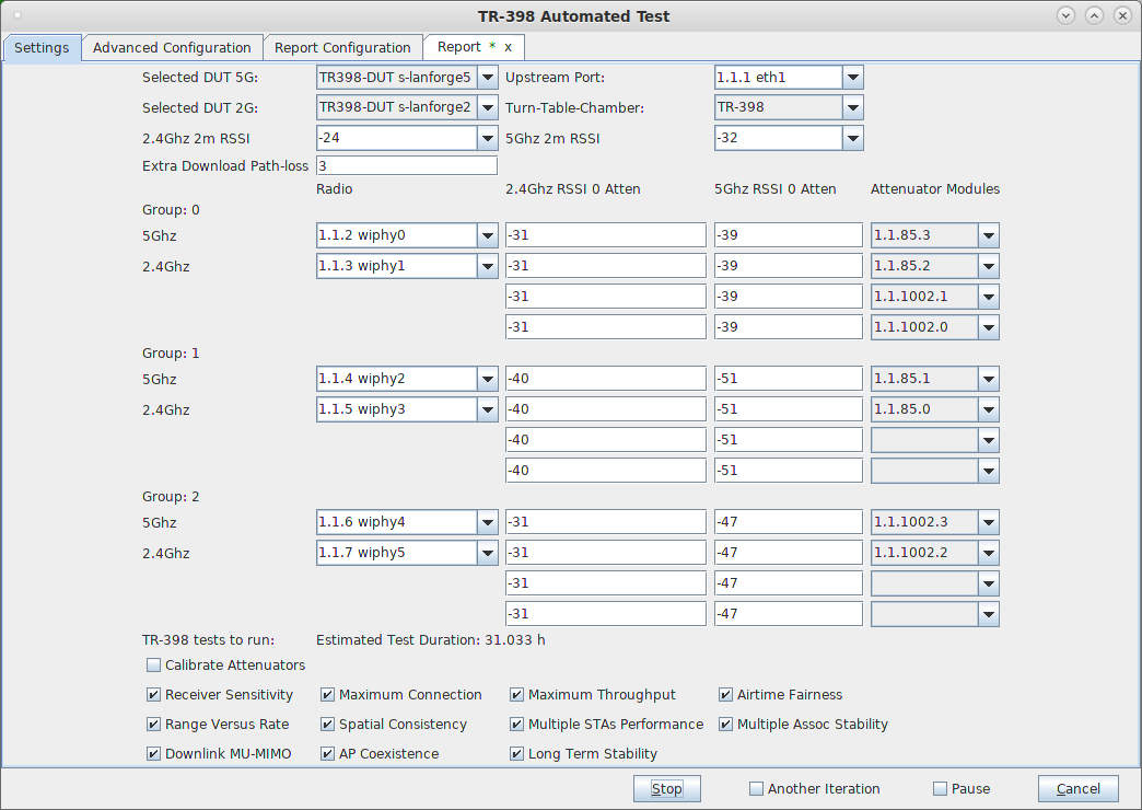
    6. Select the TR-398 test and click Run Test. You should see the TR-398 Test configuration window pop up. It will remember the last configuration for most fields. Select the 2.4 and 5Ghz DUT, turn-table chamber, and carefully associate the radios with correct attenuator modules. For the first run, we will just run the calibration test to auto-configure the path loss by adjusting the attenuators and testing RSSI: screenshot
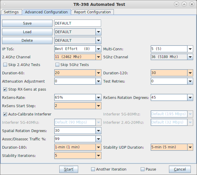
    7. Go to the Advanced Configuration tab andmake sure the channels are configured properly, and tune any other settings that you wish to modify.: screenshot
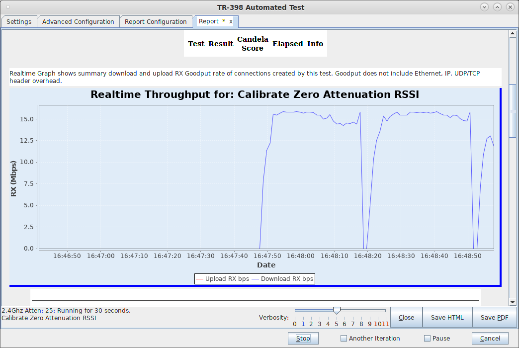
    8. When the configuration is complete, click the Start button (which will change to 'Stop' once start is clicked) to start the test. An interactive report tab will be created and will be updated as the test runs. For the first run, we will just run the calibration test to auto-configure the path loss by adjusting the attenuators and testing RSSI. If the calibration was acceptable, click Start again to save the calculated zero-RSSI attenuation values for future test runs in which you may decide to skip re-running the attenuation: screenshot
    9. After the calibration step is complete, select the desired set of test cases and click Start. The test may run for many hours. If you have the webcam configured, you can watch the rotational tests happen using the 'camorama' program (in Linux), or your own preferred USB webcam program. If using the LANforge machine to view camarama, please set the size to small so that it uses less CPU. When you click start, the Report tab is created, you can view that tab to watch the progress. screenshot
    10. When the test is complete, click the Save HTML button to save an HTML report and generate the PDF. The PDF file will be linked from the HTML page. You can also click 'Save PDF' and the browser will be directed to open the pdf file directly. Please see this example TR-398 Test Report.

Candela  Technologies, 2417 Main Street, Suite 201, Ferndale, WA 98248, USA
www.candelatech.com | sales@candelatech.com | +1.360.380.1618
Facebook | LinkedIn | Blog