Candela Technologies Logo
Network Testing and Emulation Solutions

Scripted All-in-One Cable Modem Testing

Goal: Use LANforge to test CMTS and cable-modem network (DUT).

LANforge will serve DHCP and TFTP to the DUT, generate TCP traffic to measure upload and download speeds on each modem, and generate reports. In this example, eth0 is the management port, eth1 is the upstream network port (connects to CMTS), and ports eth2-eth9 are connected to cable modems. Eth2-9 are configured for DHCP, and eth1 is configured with static IP. Eth1 is also configured to serve DHCP requests to the cable modems and other LANforge ports.
 
  1. Set up the network interfaces.
  2. Configure eth1 to serve DHCP and TFTP.
    1. Go to Status panel in LANforge GUI. Click 'Netsmith' button on the resource.
    2. Right-click in empty space and select New Router. Use default values and click OK.
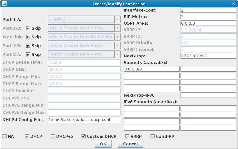
    3. Drag eth1 into the virtual router. Then double-click the virtual eth1 icon to configure DHCP. DHCP files for CMTS setups must be hand-written by the user. Configure LANforge to use this custom-dhcp config file. screenshot
    4. When Netsmith setup is complete, click Apply on the main Netsmith window to start up the DHCP service, etc. This screenshot was taken after the Layer-3 connections were set up.
  3. Configure eth2-9 to use DHCP.
    1. Go to Port-Mgr tab, double-click each port, and make sure the DHCP option is selected. Apply changes.
  4. Set up Layer-3 connections to generate the throughput tests.
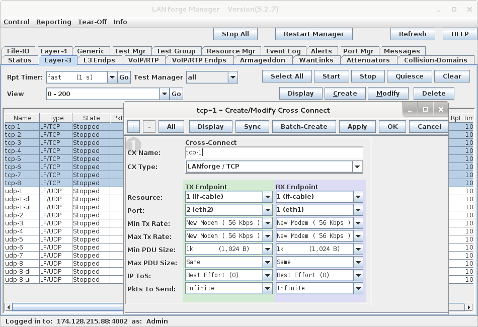
    1. Go to the Layer-3 tab, and click Create. Many cable modems are configured to do NAT and/or some firewalling, so normally you will need the connections to be TCP and to originate out from the client-side port. So, choose the LANforge/TCP connection type, and make the 'B' side eth1. Everything else can stay at the default values because we will use a script to automate the settings. screenshot
    2. Create 7 similar connections, always with B side port of eth1, and use A side ports eth2-eth9. In the Create/Modify window you can just change the name, change the port, and press apply. This will make copies of the connections.
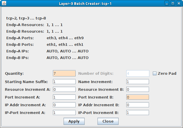
      1. You can also use Batch-Create (located in the Create/Modify window) to create these connections. screenshot
      2. Set Quantity to 7, Port Increment B to 0, and deselect Zero Pad.
      3. Click Apply.
  5. Create Test-Group to control the 8 Layer-3 TCP connections.
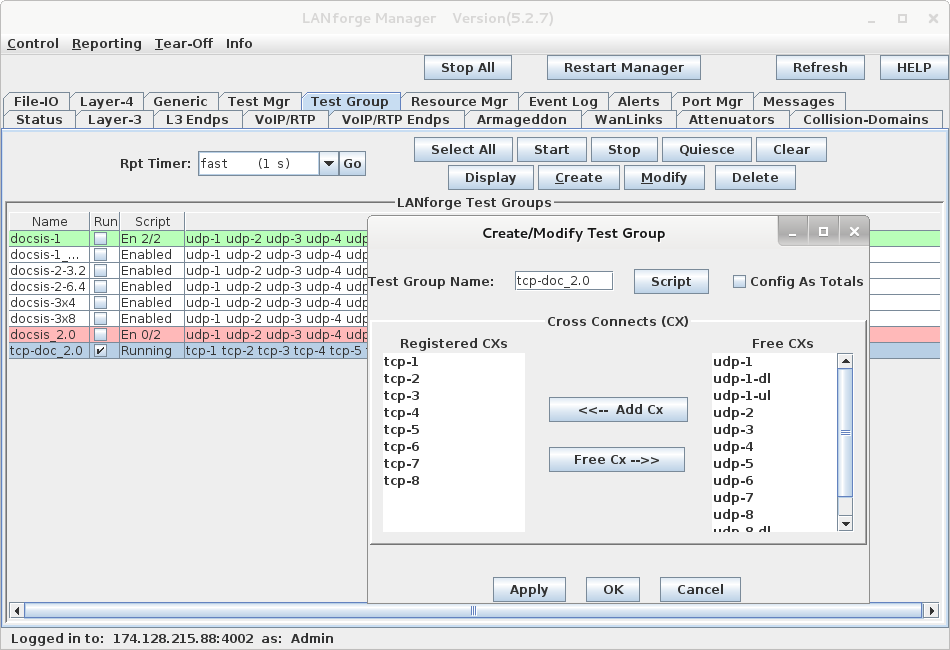
    1. Go to the Test Group tab, and click Create. Give your test group a name. Select the 8 Layer-3 TCP connections you just created in the previous step and add those to the Test Group. Click Apply and make sure the new group shows up in the Test Group table. screenshot
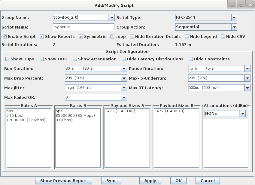
    2. We need to add a script to automate the test. Click the Script button in the Test Group create/modify window. Choose RFC 2544 script type. In this scenario, we want to test each modem one at a time, so we select the Sequential option for Group Action. The rates sections determine the speeds for each iteration. In this case, the first iteration will send from B to A at 35Mbps. This is the download test. The next iteration will upload from A to B at 17Mbps. When the two iterations are complete, the script will repeat on the next Layer-3 connection. screenshot
  6. Run the test.
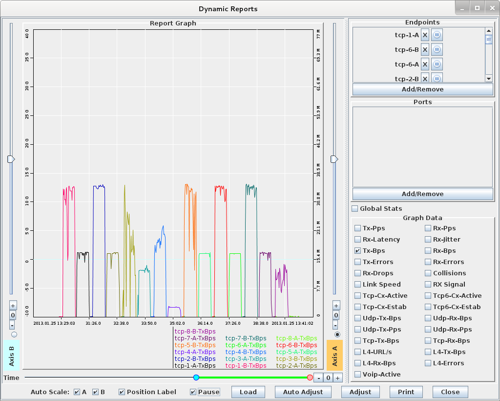
    1. To start the test, select the Test Group in the table and click the Start button. You should see a script-report window pop up, and the state should go to running. To see a live report of throughput and other values, right-click on the Test Group table and select the Dynamic Report option. screenshot
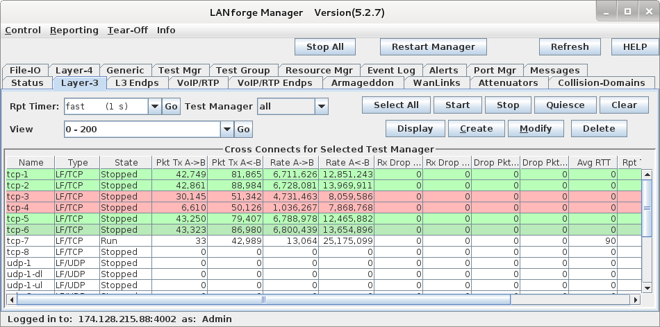
    2. View the individual connections from the Layer-3 tab. screenshot
  7. Gather reports.
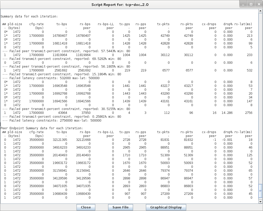
    1. When the script completes, a summary of each iteration will be shown in the Script Report window. The text may be converted to HTML, but for this particular script, the graphs are not useful because we are using Sequential mode, so just saving the text to a file or printing it is probably the best option. Note that some of these tests failed the constraints configured in the script. In this case, it is because those modems were not capable of the requested speeds. screenshot
    2. When the script completes, you could also pause the dynamic report and print it. For an electronic copy, use a PDF printer to create PDF files instead of printing to paper.
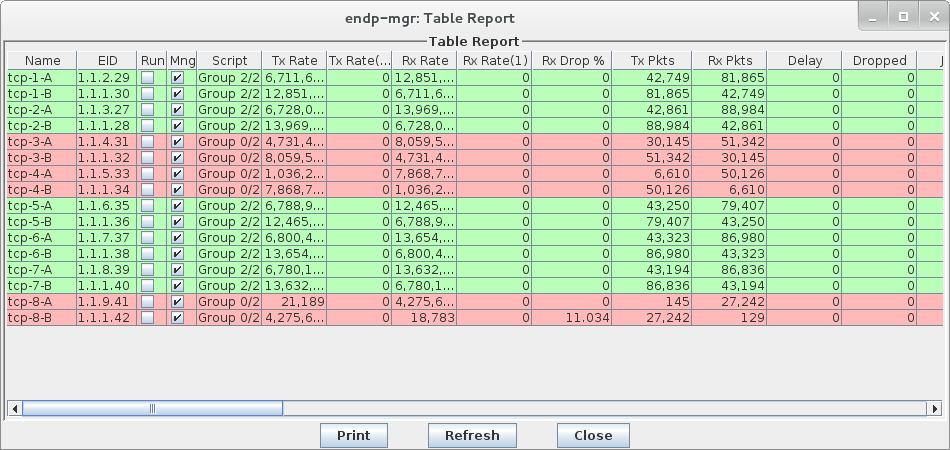
    3. The Layer-3 tab will color-code the 8 connections, with red meaning fail, and green meaning pass. You can print the connections you are interested in by selecting them in the table and using right-click → Table Report. This report can be printed or otherwise saved. screenshot

Candela  Technologies, 2417 Main Street, Suite 201, Ferndale, WA 98248, USA
www.candelatech.com | sales@candelatech.com | +1.360.380.1618
Facebook | LinkedIn | Blog