CT714 LANforge-Attenuator with 4 Attenuator Channels: .005 GHz - 6 GHz
The CT714 RF Attenuator is used to attenuate (decrease) the
RF signal between wireless devices. A summary of the technical specifications is below:
| Max RF Power: | +28 dBm |
| Impedance: | 50 Ω |
| Frequency Range: | 0.005 GHz – 6.0 GHz |
| Attenuation Range: | 0 – 95 dB |
| Attenuation Steps: | 0.5 dB increments |
The CT714 may be controlled through software access over the USB-Serial port or Ethernet. The included
LANforge software suite supports automated scripting as well as manual configuration
of the attenuator modules.
The CT714 should be used with an RF enclosure to prevent the devices
connected to the attenuator from bypassing the RF attenuator using over-the-air
RF leakage.
The CT714 has no moving parts and will fit into a small travel bag or briefcase for easy portability.
The CT714 includes a USB Cable for both management and power supply. If powering many attenuators,
a powered USB hub should be used. PoE Ethernet is also supported.

Larger Images:
front
top
side
NOTE: This product may have a different hardware
configuration than the system pictured above.
Refer to your official quote for details. |
"

NOTE: This product may have a different hardware
configuration than the system pictured above.
Refer to your official quote for details. |
Candela Technologies Inc., 2417 Main Street, Suite 201, P.O. Box 3285,
Ferndale, WA 98248, USA
www.candelatech.com | sales@candelatech.com | +1 360 380 1618
Example Network Diagram

The LANforge attenuator sits between two RF systems, often a WiFi AP on one side and WiFi Station
on the other. The attenuator and WiFi stations are connected by shielded SMA-Male cables. Adjust the
attenuation as desired either with the LANforge GUI or direct access over serial.
Candela Technologies Inc., 2417 Main Street, Suite 201, P.O. Box 3285,
Ferndale, WA 98248, USA
www.candelatech.com | sales@candelatech.com | +1 360 380 1618
Quick Start Guide
- Connect the CT714 to a Linux system running LANforge with the included USB cable. The USB cable allows control of the CT714.
The USB cable also provides power so no other power cable is required. PoE Ethernet connectivity may also be used.
- Connect the attenuator pairs: One side to one system and the other side to another system or antennas.
- Open a LANforge GUI and connect to the Linux system with the CT714.
- If using USB, the attenuator should be automatically discovered. If using Ethernet, then click
the Discover button. In the Attenuator tab, you should see the CT714 device appear.
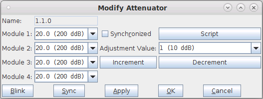
Modify it to set attenuation values manually
and/or configure a script to change attenuations automatically.
- One useful feature for the CT714 is the Rate vs Range test in Chamber View. The second screenshot below
shows the possible options this feature gives. For more information, please see
Testing Rate vs Range throughput for a WiFi Device.
Candela Technologies Inc., 2417 Main Street, Suite 201, P.O. Box 3285,
Ferndale, WA 98248, USA
www.candelatech.com | sales@candelatech.com | +1 360 380 1618
LANforge-Attenuator Related Images
LANforge Attenuator Configuration Screen
LANforge Attenuator Rate vs Range Test
Candela Technologies Inc., 2417 Main Street, Suite 201, P.O. Box 3285,
Ferndale, WA 98248, USA
www.candelatech.com | sales@candelatech.com | +1 360 380 1618
Software Features
- Using Rate vs Range, an AP can be tested how well it can transmit packets at different signal levels for transit and receive.
- Emulate mesh node distance.
- Test device roaming between APs.
- Test how well the AP can receive packets with different MCS at different RF Signal levels.
Hardware Specification
- RF Attenuator with 0.005 Ghz to 6 Ghz.
- USB-Serial console (115200 8 N 1) for scripting and automated control.
- Weight: 1.6 lbs or .714 kg.
- Dimensions: 7 x 3.5 x 1 inches Metric: 180 x 90 x 25 mm.
- Operating Temperature: 0 ~ 60°C.
- Operating Humidity: 10 ~ 90%.
- Certification: RoHS.
| Max RF Power: | +23 dBm |
|---|
| Impedance: | 50 Ω |
|---|
| Frequency Range: | 0.3 GHz – 6.0 GHz |
|---|
| Attenuation Range: | 0 – 95.5 dB |
|---|
| Attenuation Steps: | 0.5 dB increments |
|---|
| Insertion Loss (dB): | Frequency | Typical | Max |
|---|
| 5 Mhz | 4.2 | 5.0 |
| 2400 Mhz | 6.3 | 6.5 |
| 6000 Mhz | 10.9 | 13.0 |
| Attenuation Accuracy (dB): | Frequency | Conditions | Typical | Max |
|---|
| 5 - 2000 Mhz | 0.25 - 20 | ±0.25 | ±(5.5% of Atten. + 0.25) |
| 20.25 - 60 | ±0.50 | ±(2.0% of Atten. + 0.90) |
| 60.25 - 90 | ±0.75 | ±(3.5% of Atten. + 0.70) |
| 2000 - 4000 Mhz | 0.25 - 20 | ±0.20 | ±(5.5% of Atten. + 0.25) |
| 20.25 - 60 | ±0.30 | ±(2.0% of Atten. + 0.70) |
| 60.25 - 90 | ±0.40 | ±(3.0% of Atten. + 0.90) |
| 4000 - 6000 Mhz | 0.25 - 20 | ±0.15 | ±(6.5% of Atten. + 0.15) |
| 20.25 - 60 | ±0.35 | ±(3.5% of Atten. + 0.45) |
| 60.25 - 90 | ±0.65 | ±(3.5% of Atten. + 0.90) |
List Price: $4,995
List Price with 1 Year support (17%): $5,844
Additional Products
For a more complete WiFi testing setup, you may wish to consider the
CT711 RF Noise generator,
CT712 RADAR Simulator,
CT523 and
CT525 series WiFi traffic generators.
Candela Technologies Inc., 2417 Main Street, Suite 201, P.O. Box 3285,
Ferndale, WA 98248, USA
www.candelatech.com | sales@candelatech.com | +1 360 380 1618
Last modified: Wed Jun 11 11:35:01 PDT 2025

