Candela Technologies Logo
Network Testing and Emulation Solutions

Calibrating TR-398 Issue-4 and Mesh on a 4-Chamber Setup

Goal: Setup and run a TR-398 Issue 4 test for an AP using a version of the LANforge CT523c or similar system in order to test how well the AP can handle the various test cases specified in the TR-398 Issue 3 test document. TR-398 Issue 4 is Issue 3 with WiFi 7 support.

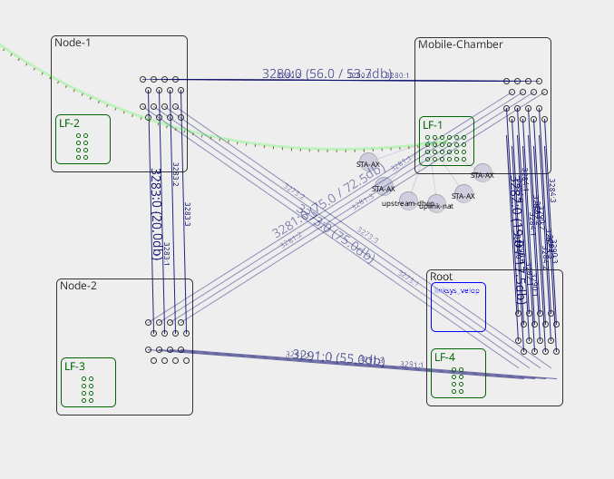
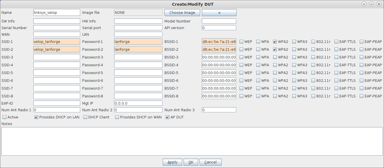
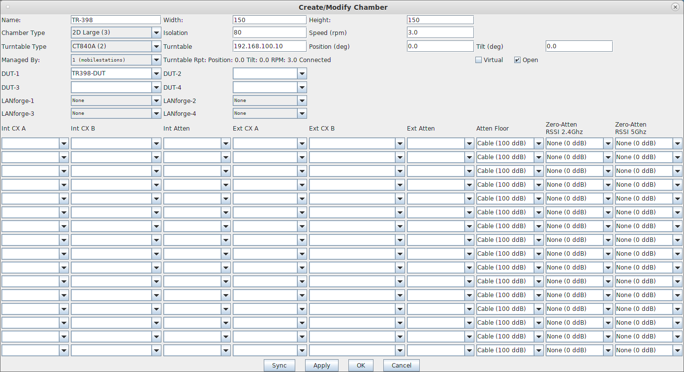
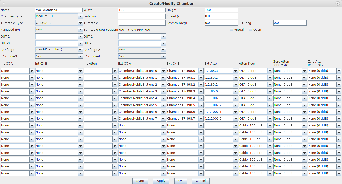
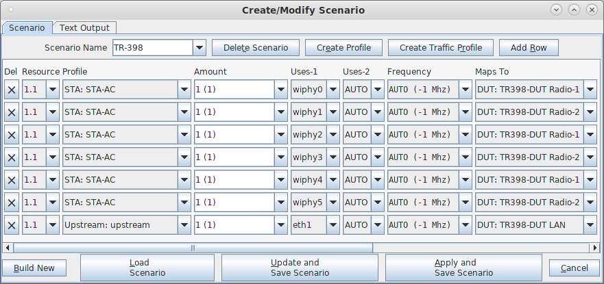
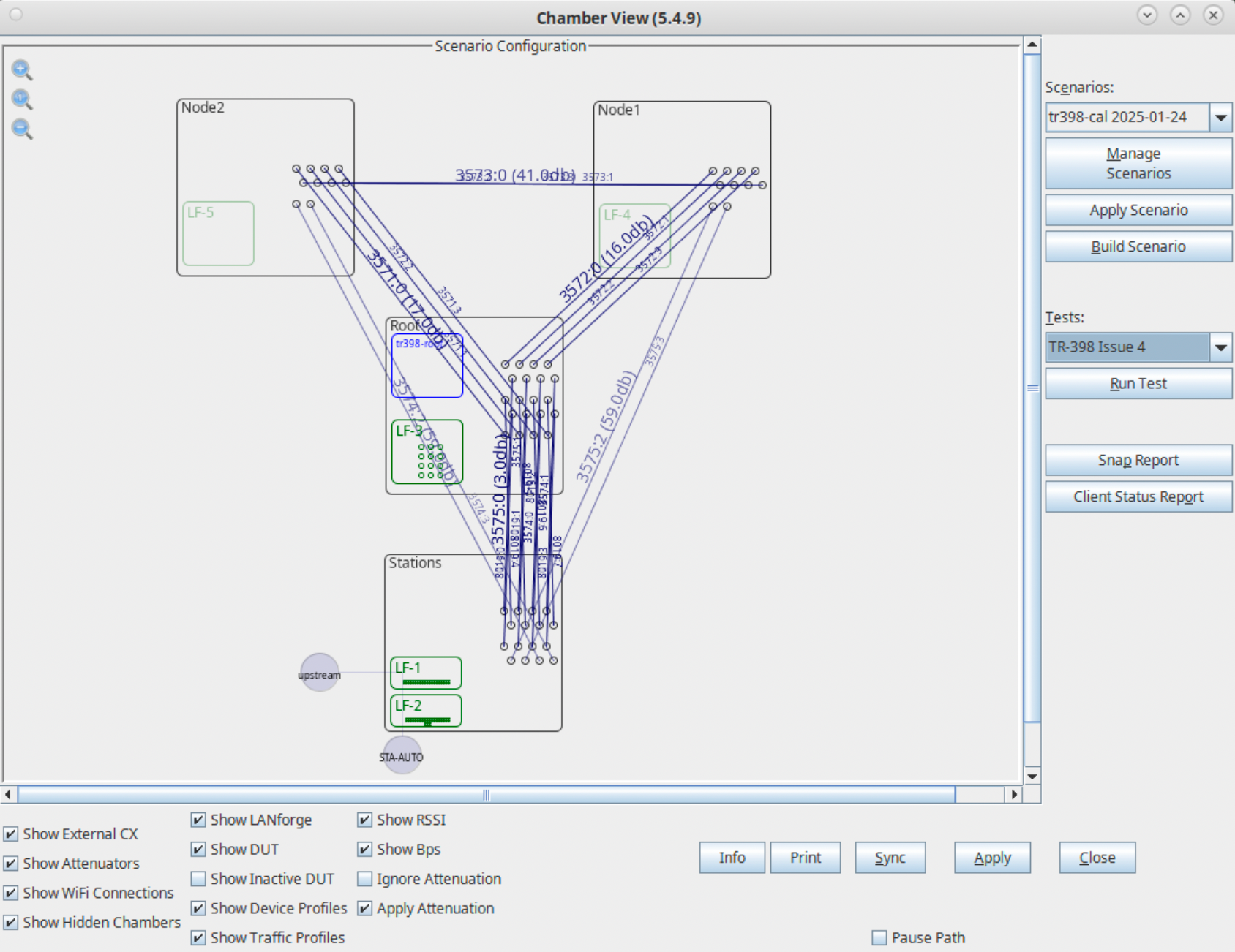
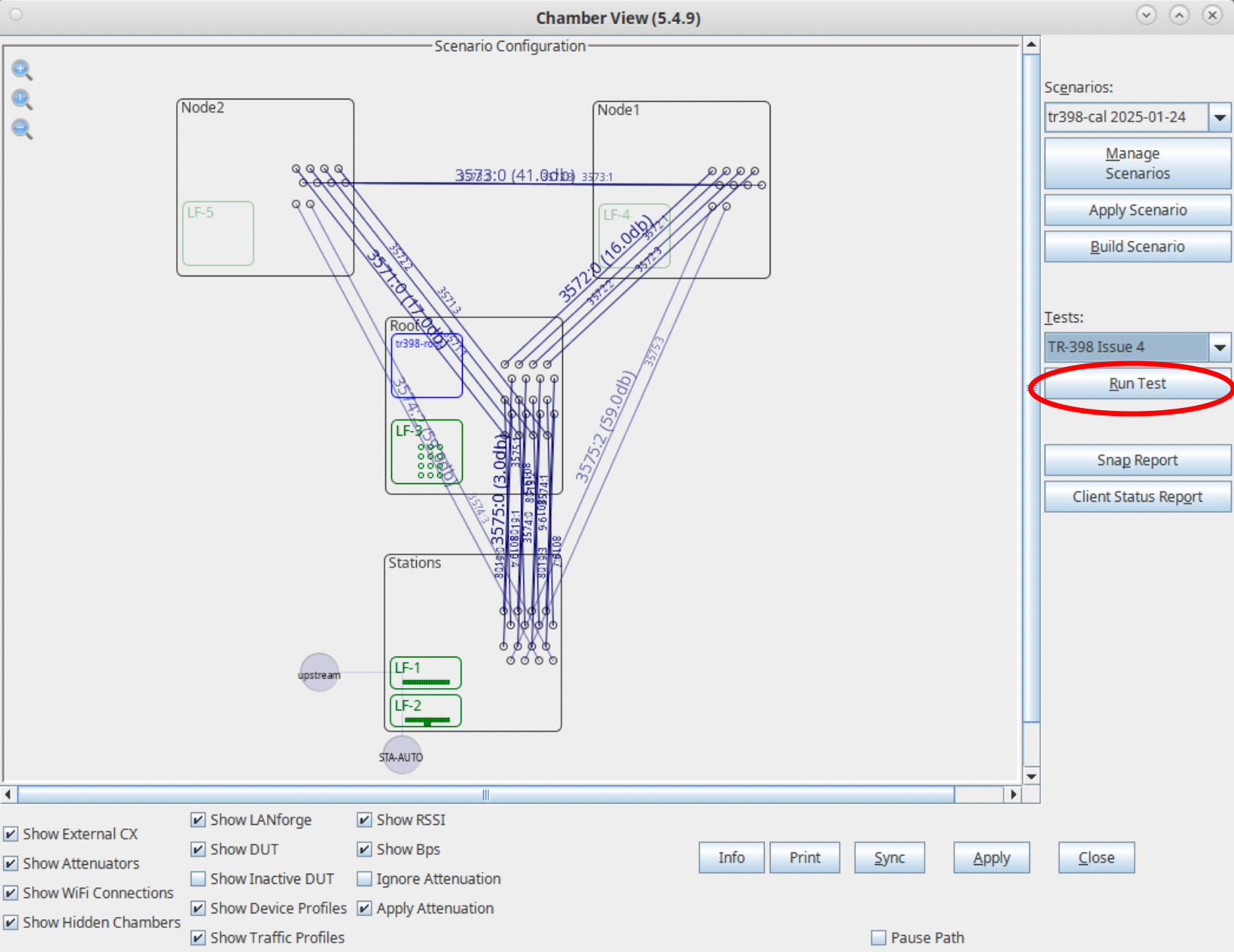
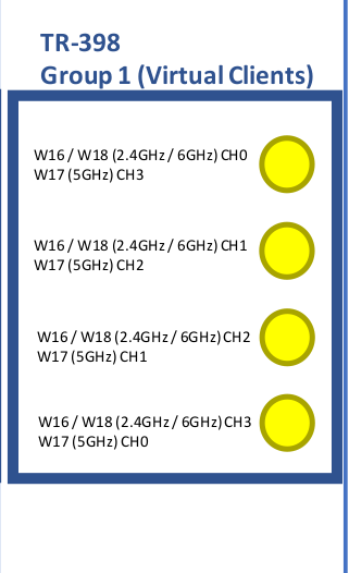
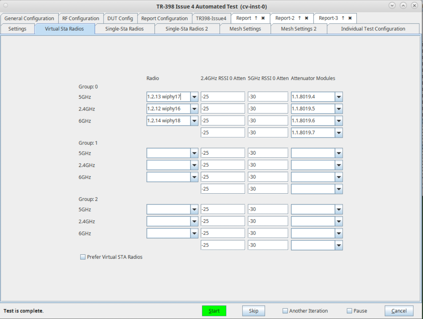
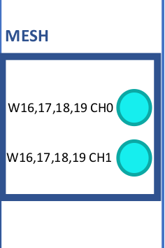
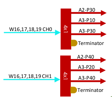
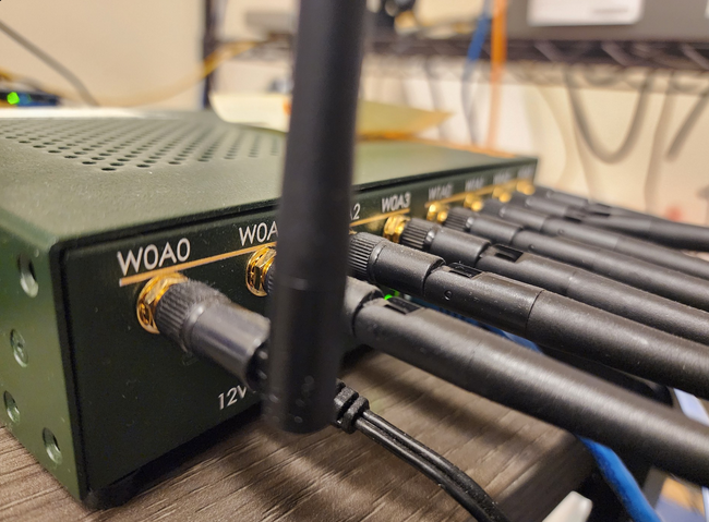
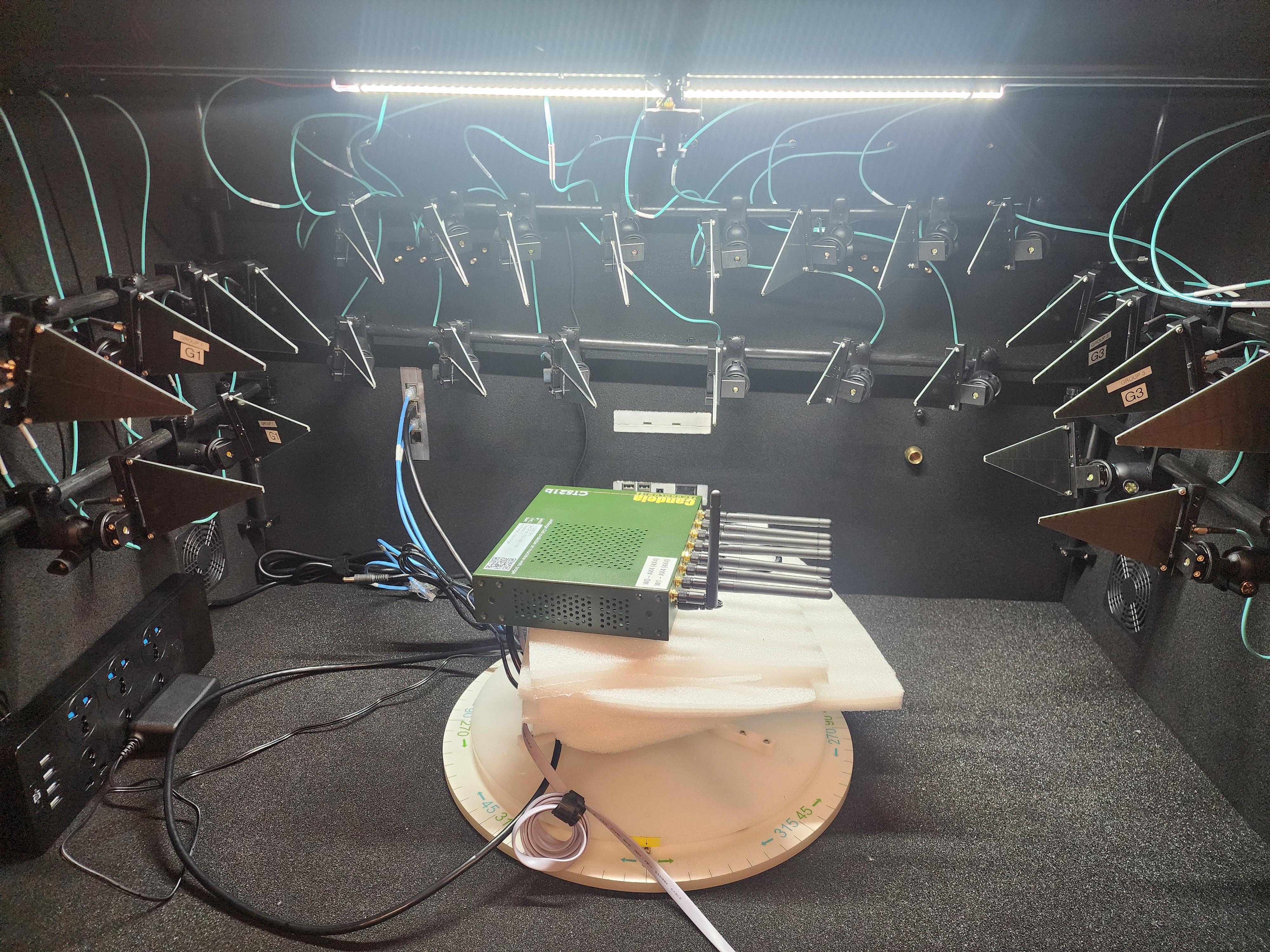
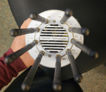
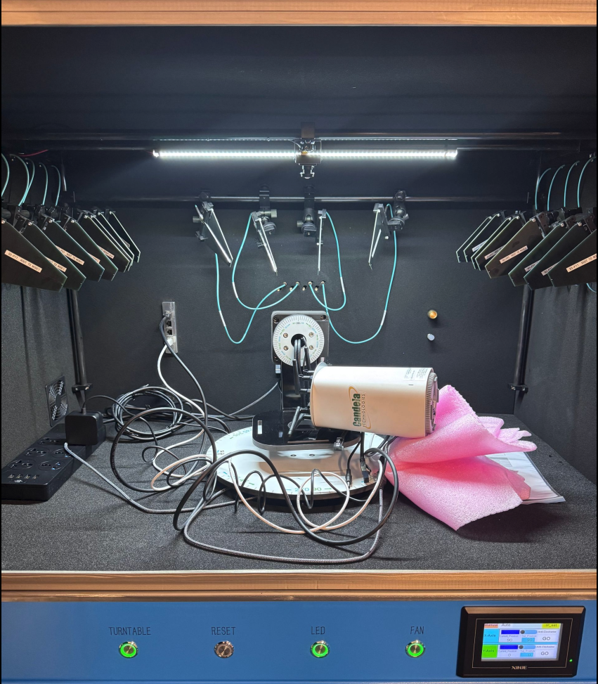
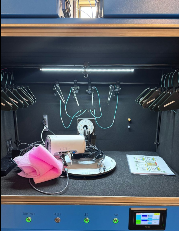
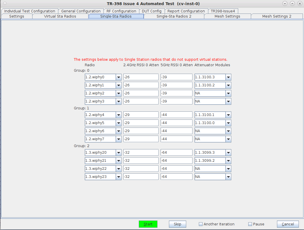
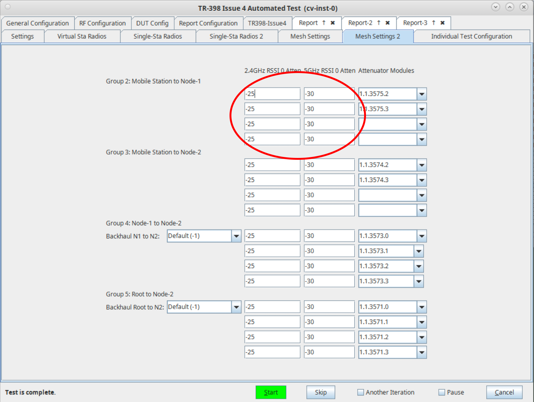
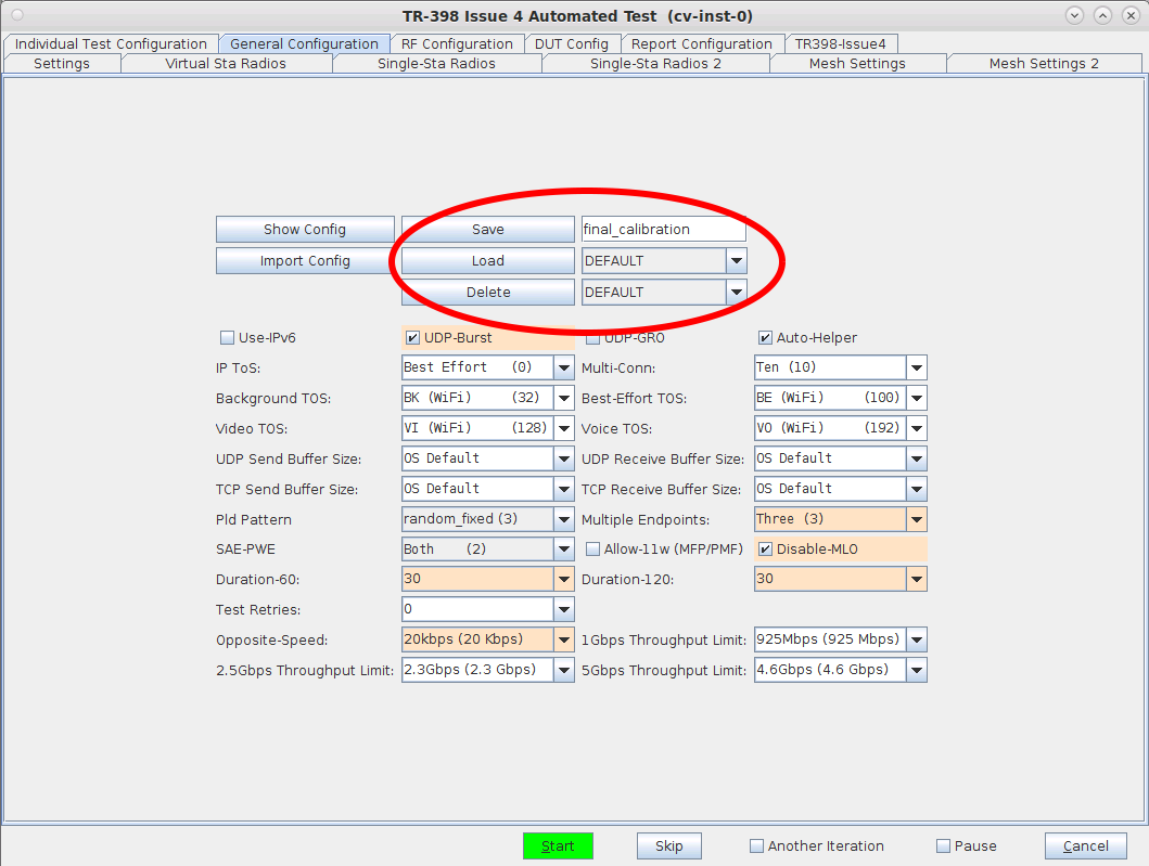
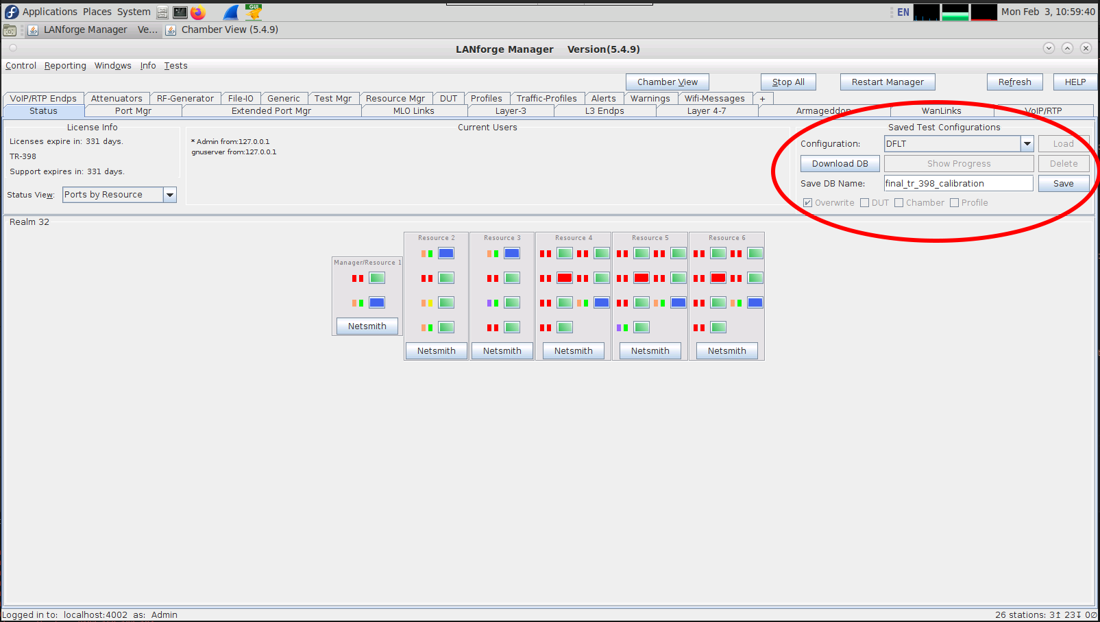
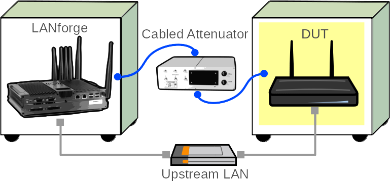
In this test scenario, a LANforge cluster (of 4+ LANforges) is used to emulate different station and AP scenarios and generate and receive traffic with an AP. This example assumes user has some experience with Chamber View, and has an appropriate LANforge system (fit for TR-398 Issue 3/4), programmable attenuators like the CT714 and some isolation chambers like the CT820a and CT840a. Please contact support@candelatech.com for assistance in setting up the TR-398 testbed or configuring your current testbed to match TR-398 needs as close as possible.

 
  1. Configure Chamber View for TR-398 and Similar Tests. Below is a rough step by step of how to make a scenario. For more help on scenario setup, please visit the following link: Chamber View: Basic AP Testing (this cookbook will need a working scenario)
    1. Open Chamber View by clicking on the 'Chamber View' button in the LANforge-GUI window. If you have an appropriate scenario already created, please skip to the next section, otherwise you will need to build a scenario that matches your system. Right-click in Chamber View to create various objects. Below is an example of a Chamber View TR-398 scenario. The testbed to be calibrated will not necessarily match the one below. screenshot
    2. Create a Device Under Test (DUT) Profile that matches your AP. The BSSID is important to configure so that LANforge knows when it is connected to the correct AP. In a mesh scenario, 3 DUT objects may be created, one for each of the mesh AP chambers. screenshot
    3. Create a chamber object to hold the DUT and add the DUT to that chamber. If you have no chambers, create a fake chamber, but the test will not be isolated and may not function as desired. The turntable configuration is different for different models of chambers, this example (bare IP address) is for the CT840a chamber. screenshot
    4. Add the LANforge to the chamber object made above. Add connections from this chamber to the DUT chamber, specifying the proper Attenuator modules. Please note we use the 'OTA' attenuation floor since we have OTA connection between DUT and antennas inside the DUT chamber. Please view our other cookbook on setting up attenuator connections in LANforge. screenshot
    5. Configure a Chamber View Scenario and add the STA profile (mapped to desired wiphyX radio and DUT). Add an upstream profile mapped to DUT LAN side (or possibly WAN side if that is more appropriate for your DUT). screenshot
  2. For TR398 tests, the DUT AP's front should face the antennas for the Group-1 stations. Or, optionally, one can use the Advanced configuration tab to specify the default turntable angle for non rotational tests.
  3. Open Chamber View by clicking on the 'Chamber View' button in the LANforge-GUI. Load appropriate scenario by clicking on the drop-down above Manage Scenarios and selecting the scenario to be used. Click Apply Scenario, then Build Scenario. Below is an example of a loaded scenario. screenshot
  4. Select the TR-398 Issue 4 test from Tests dropdown in the right panel. Then click Run Test. screenshot
  5. The following window below should pop up. In the Settings tab, set slots Selected DUT 5G, Selected DUT 2G, and Selected DUT 6G the according BSSIDs found in the 'Root' Chamber. Also set the upstream port and multicast port if used. In this example, the upstream port is the eth2 port on the Resource 1 (Manager) LANforge. Select Skip 6Ghz Test and Skip MLO Tests , those will not be run during calibration. screenshot
  6. Configure the Virtual Sta Radios tab.
    1. Select the Virtual Sta Radios tab. This tab is for radios that can support more than 1 virtual station on them (either AC, N, some AX). There are 3 possible groups since TR398 uses 3 groups in total. These groups will be labelled on the diagram that Candela provides to you as TR-398 Group X (Virtual Clients) , where X can be 1, 2, or 3. If the groups are not on your diagram, you do not have virtual stations. screenshot
    2. Below is an example of a testbed only having 1 group of virtual stations, which have been filled out in the Radio column within the settings. screenshot
    3. Lastly, fill out the Attenuator Modules column, in the right-most section. On the testbed diagram, the Group X should be pointing to some specific attenuator modules. Typically, LANforge attenuators have modules, 2 physical ports on the attenuator per module. Usually, P10 and P11 are module 0, P20 and P21 are module 1, P30 and P31 are module 2, and P40 and P41 are module 3. In the picture above, right-most column, attenuator modules are in the format 1.LANforge-Resource-No.Attenuator-Serial-No.Module-No. The serial number of an attenuator can be found physically on the side of the attenuator. The diagrams group should point to a port and that corresponds to the module being used. The picture above shows an example of the completed attenuator module. Below is what the diagram showed to get those results above. screenshot
  7. Configure the Single-Sta Radios. This tab is for stations that only support 1 station at a time. On the testbed diagram, this may be labelled as Real Clients stations and these real clients can be split upto 3 groups.
    1. Below is an example of what the real clients may look like on the testbed diagram provided. screenshot
    2. Below is an example of what the radios above would look like filled out in the first page of the Single-Sta Radios tab of the TR-398 Issue 4 window. screenshot
    3. Below is the 2nd (and final page) of the above example. Using the same technique as used in the Virtual Sta radios, trace the radios to their according attenuator module on the testbed diagram to fill out the correct Attenuator Module on the Single-Sta Radios page. screenshot
  8. Configure the Mesh Settings and Mesh Settings 2 tabs. If the test bed being setup has no need for Mesh, please skip this step.
    1. Select the Mesh Settings tab. The 2.4G and 5G columns should have default values of -25 and -30 respectively. Typically, under the 'Radio' section in this page, if 'Backhaul' is defaulted to '-1' it is best to leave that as is. Fill out the 'Atten Modules' column for each group (using ports 0-3 for each attenuator). To find out the correct attenuator, trace the testbed diagram to find out which attenuator connects which radios. Sometimes radios for Mesh and TR-398 will be shared (they are NOT shared in this case). One way they may be shared, for example, would be if 'Group 1' (in this Mesh section), may use the attenuator and radios used in 'Group 2' of the Virtual Sta Radio Settings tab. The attenuator may also be split to be both TR398 and Access (A3/T1) too, belonging in both Virtual Sta Radio Settings and Mesh Settings. However, there are multiple ways that attenuators and radios can be shared. screenshot
    2. Fill out the Mesh Settings 2 tab similarly to Mesh Settings 1 screenshot
    3. Below is an example of how mesh radios may show up on the testbed diagram provided. screenshot
    4. Below is an example of how those mesh radios from above may are represented on the testbed diagram to connect to attenuators. screenshot
  9. Position the LANforge to get ready for calibration. There are 2 ends of calibration, the AP and the Station. Both sides will be LANforges. Typically the LANforge that is the station can be any LANforge type, while the AP may be a smaller LANforge, such as a 521b, 521a, or AT7. But usually testbed setups will have designated LANforges within each chamber and those are what will be used for the stations LANforge. Each calibration test needs 3 trials done. After each trial, the stations LANforge and the AP LANforge will be rotated to get the best RSSI average. As long as the LANforge is not cabled into the wall in any way, it can be rotated.
    1. Positioning of 521b, upclose, with Wiphy 0 Channel 0 (labelled as W0A0) sticking up screenshot
    2. Positioning for 521b/521a (521b shown below). The 521b must have the Wiphy 0, channel 0 (W0A0) sticking up. The chamber antennas that are cabled up the testbed (the ones that aren't cabled to anything can be left as is), must be pointing directly at W0A0. The calibration may also do better if the LANforge is higher up, this gives a better chance for the chamber antennas to access single W0A0 antenna. The LANforge can be propped up with foam or cardboard. When the LANforges are rotated for each trial, the chamber antennas should be repositioned to point to W0A0. screenshot
    3. Below is an upclose of the top hat of the AT7 and it's labels. On the right side is 6Ghz W0-W4, the left side has 2.4/5G W0-W3. On the 2.4/5G side, W0 labelled there only applies to 2.4, while 5G W0 is on the opposite end (labelled W3). Similarly, the W3 labelled on the 2.4/5G AT7 is the 2.4G's actual W3, but 5G's actual W3 is labelled W0. This is important so the user knows which antennas should be pointed up for calibration. screenshot
    4. Below is an example of an AT7 positioned for calibration. The best way to calibrate with the AT7 is to lay it flat, with the W0 and W3 label sticking up on the 2.4/5 side, which corresponds to both 2.4G and 5G W0 antennas sticking up. The rest of the antennas can be facing as down as possible and away from the two pointing up. screenshot
    5. Below is an example of the same AT7, rotated once. After rotation, the AT7 should still maintain a position where the W0 for both 2.4G and 5G stick up, with the other antennas pointed down and away from the two sticking up. screenshot
  10. Establish all the tests that need to be done. From above, we filled out Virtual-Sta radios, Single-Sta radios, and Mesh radios. That means that all the attenuators and pathways that correspond to those need to be calibrated. Below are all the calibration tests that need to be run in the Settings tab. Run each of the checkboxes one at a time to make sure each test passes. Make sure to check Skip 6Ghz Tests and Skip MLO test since those tests are not needed for calibration. screenshot
  11. Run each of the tests checked, that applies to your testbed setup. In the example image given above, all the tests under TR-398 Tests to Run, would be run one checkbox at a time.
    1. For each test, as described earlier in the cookbook, position both the LANforges (if the LANforge is not hard-cabled into the chamber) in their according position to their model LANforge. Each of the checkboxes requires 3 trials of the test between 2 chambers, where 1 chamber is the LANforge station and 1 is the LANforge AP. Between each trial, both the station LANforge and the AP LANforge should be rotated, if possible.
    2. In this cookbook example, the first test we have is Calibrate Single Sta Attenuators. This means that the test is run between the Single-Sta radios in the stations chamber (LF1 Group 1, Group 2, Group 3) and the LANforge in the Root Chamber. This test is then run, the data from the 3 group's 2.4GHz RSSI 0 Atten and 5GHz RSSI 0 Atten is recorded, the station LANforge and AP LANforge is rotated (if possible, if not just rotate 1), and the test is re-run with the same process done 2 more times (with a total of 3 trials). The averages are then taken for Group 0, Group 1 and Group 2 (2.4G and 5G) among the 3 trials and then typed in for the 6 values under the Single-Sta Radios tab, as shown in the picture. screenshot
    3. This same process happens for all the other checkbox tests.
  12. Another example of calibration would be for the checkbox Mesh Sta to Node-1 Attenuators. In this case, the LANforge station would be in the Stations chamber and the LANforge AP would be placed in the Node-1 chamber. Since the testbed will most likely have the stations in the Stations Chamber, and the AP is unlikely to be to the Stations Chamber, this makes the most sense for calibration. After the AP is placed in the Node-1 chamber, the chamber antennas are pointed to the W0A0 antenna(s), and 3 trials are run with rotations of the AP after each trial. After each trial the 2.4G and 5G values populated in the 2.4G RSSI 0 Atten and 5G RSSI 0 Atten are recorded. At the end of 3 trials, the average is taken and manually entered into the 0 Atten RSSI spot for both 2.4 and 5. Below in the red circle area is where the RSSI values will be populated after each trial and where the final average should be filled out (removing the last auto-filled RSSI value and inputting the 3-trial average instead). screenshot
  13. At this point, all the 0 Atten values should be filled out. Save these values as a database in both the TR398 window database and the LANforge 'Status' tab database sections. It may also be good to take screenshots of all the final values and save it off-LANforge.
    1. Below is a picture of how to save as a database in the TR-398 window. screenshot
    2. Below is a picture of how to save as a database in the Status tab of LANforge. screenshot
    3. Below is a picture of what an outline might look like for documentation of the 3 trials. This outline is just for the Mesh calibration tests. screenshot
  14. Run a TR-398 Issue 4 throughput test. Select the 6.2.2 Maximum Throughput checkbox to run the test. After verifying the throughput test is working as expected, select and run other tests as desired. screenshot
  15. When the test is complete, click the Save HTML button to save an HTML report and generate the PDF. The PDF file will be linked from the HTML page. Another option is to click 'Save PDF' and the browser will be directed to open the pdf file directly. Please see this passing example TR-398 Issue 2 Maximum Throughput Test Report .

Candela  Technologies, 2417 Main Street, Suite 201, Ferndale, WA 98248, USA
www.candelatech.com | sales@candelatech.com | +1.360.380.1618
Facebook | LinkedIn | Blog