Candela Technologies Logo
Network Testing and Emulation Solutions

Multiple Physical Port Testing - CT970-48 Example

Goal: Use LANforge and a managed ethernet switch to create 48 unique WAN emulations.

In this example, LANforge is paired with a managed ethernet switch to create 48 unique WAN emulations. Each of the 48 ports on the ethernet switch can be connected to an end-user device such as a PC or networked gaming console to provide 48 independent emulated links each with their own set of network impairments. Please see the CT970-48 product description for more details.
NOTE: If you are attempting to run this test scenario, you will need a LANforge license key that enables the correct number of WanLinks. Please contact us at support@candelatech.com for assistance.
 
  1. Download the CT970-48 configuration to your LANforge system. We have provided the LANforge database and managed switch configuration for this example to simplify the setup.

    You can download all of the CT970-48 configuration files to your /home/lanforge/DB/CT970-48 directory.
    1. NOTE: This LANforge database uses eth0 as the Management port and eth2 as the VLAN trunk port. If you need to modify these, please contact us at support@candelatech.com for assistance.
    2. NOTE: The managed switch referenced in this example is a Netgear FSM7352SNA ProSafe 48-port 10/100 L3 Managed Switch.
  2. Save your existing database, then load the new database into your LANforge system.
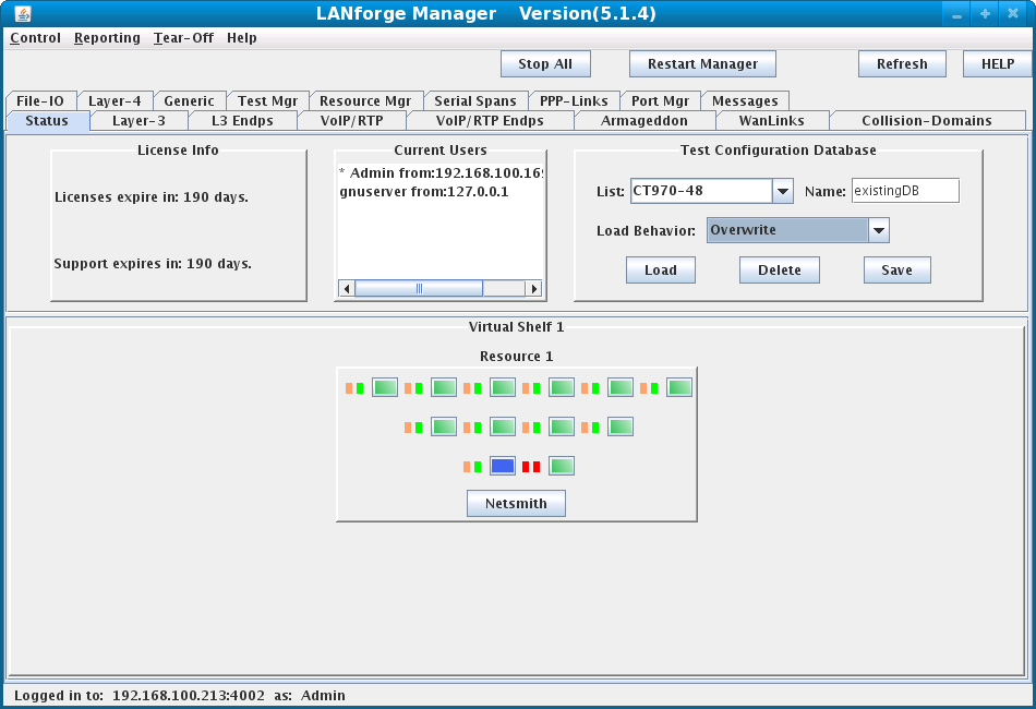
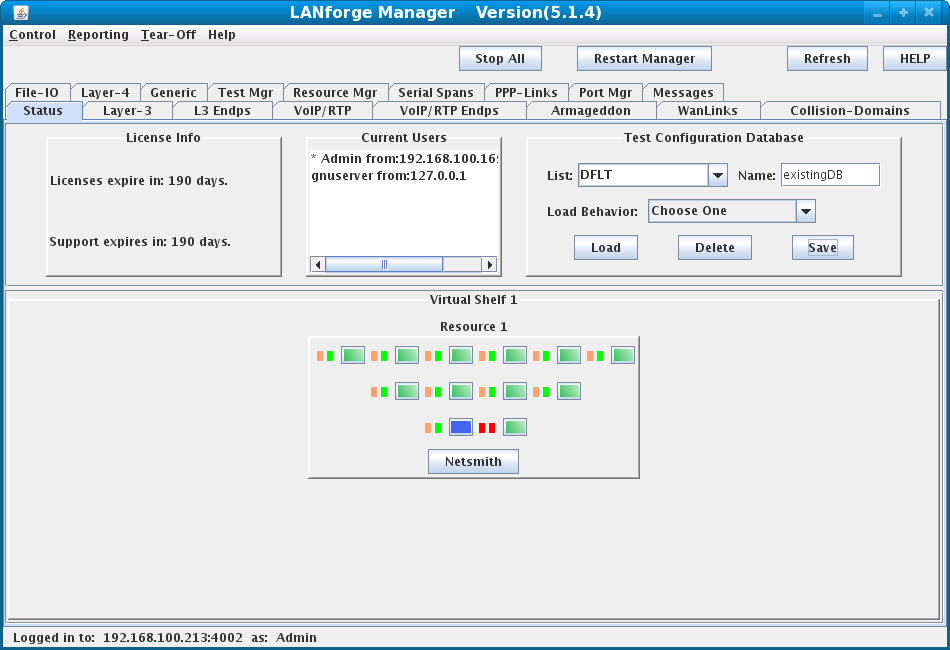
    1. On the Status tab, under the Test Configuration Database Name field, type in a name for your existing configuration, then select the Save button. screenshot
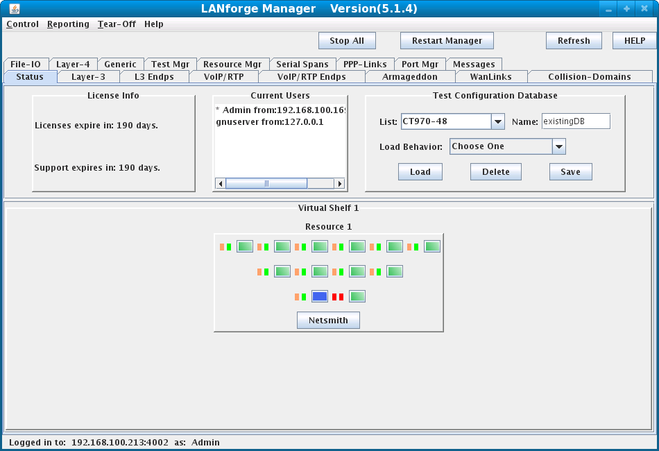
    2. Select CT970-48 from the Test Configuration Database List box. screenshot
    3. Select Load Behavior Overwrite. screenshot
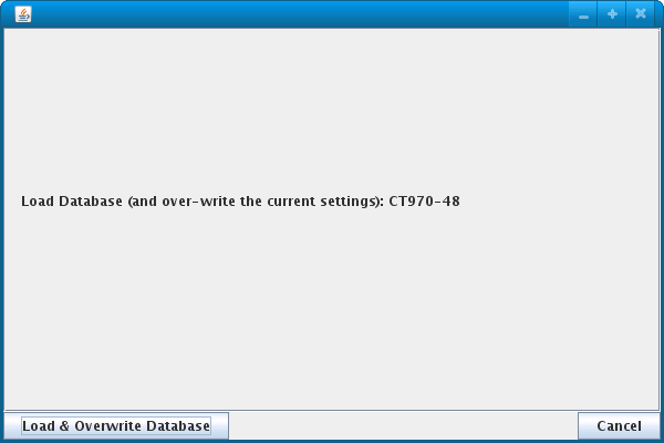
    4. Select the Load button and acknowledge the confirmation pop-up message. screenshot
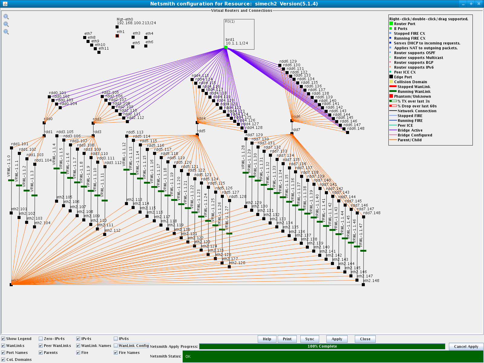
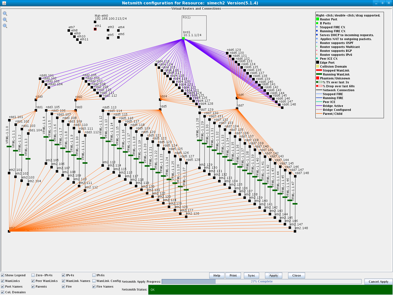
  3. After LANforge is finished loading the new database, open Netsmith to view the 48 WanLinks and modify if necessary.
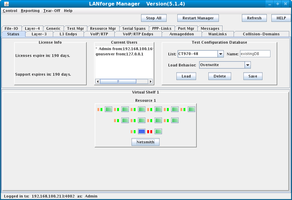
    1. On the Status tab, under Resource 1, select the Netsmith button. screenshot
    2. If any changes are made to Netsmith, then select the Apply button to commit the changes to the LANforge server. screenshot
  4. When the 48port-sw-config.txt is loaded into the Netgear FSM7352SNA switch, port 52 on the switch is configured as the VLAN trunk which will connect to LANforge port eth2.

    Each switch port and VLAN correspond to a WanLink in LANforge. Here, incoming traffic on switch port 1 is tagged for VLAN 101 and sent out switch port 52 to LANforge eth2 then on to WanLink VRWL-1.1.0 via endpoints eth2.101 and rdd1.101.
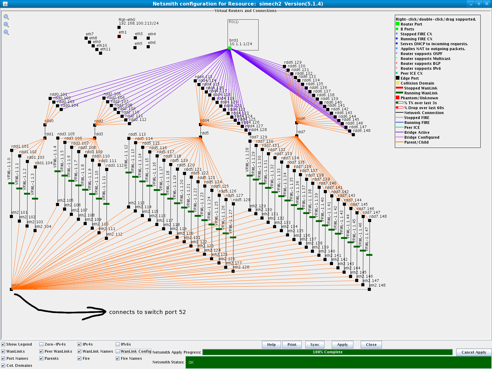
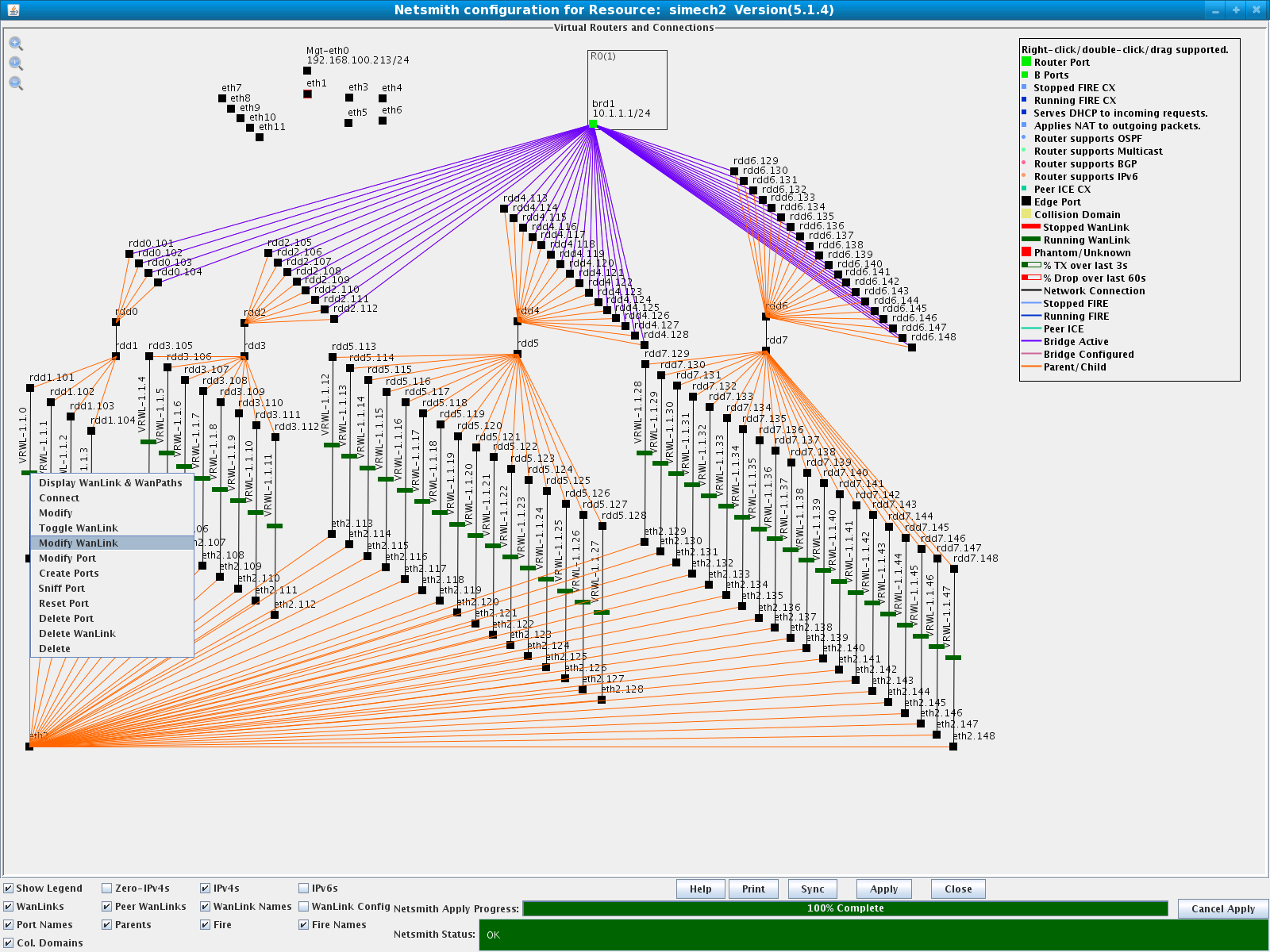
    1. Connect LANforge port eth2 to the FSM7352SNA switch, port 52 which is trunking vlans 101 - 148 to the LANforge system. screenshot
    2. Here, each WanLink can be modified to have its own unique impairment profile so that each end-device has a different upstream connection. screenshot
    3. If any changes are made to Netsmith, then select the Apply button to commit the changes to the LANforge server. screenshot
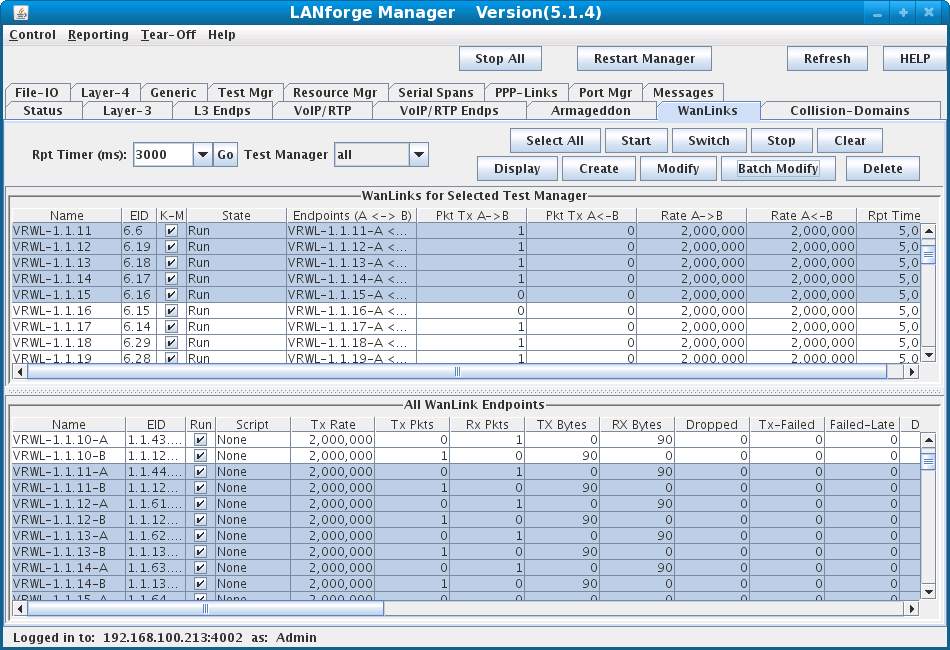
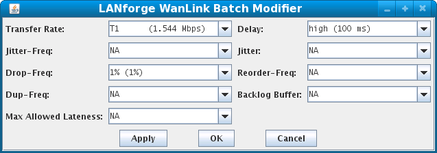
    4. Alternatively, a group of WanLinks can be modified together using the Batch Modify on the WanLinks tab in the main LANforge GUI. Highlight the group of WanLinks that you want to modify, then select Batch Modify to modify the highlighted set of WanLinks. screenshot
    5. The Batch Modifier will apply changes to the group of highlighted WanLinks. screenshot
  5. In this example, any end-devices connected to switch ports 1 - 48 can communicate with each other. Here, an end-device such as PC1 connected to switch port 1 can communicate to PC2 connected to switch port 2 through the network path:
    PC1 - switch port 1 - vlan 101 - switch port 52 - LANforge port eth2 - WanLink VRWL-1.1.0 - Virtual Router R0 - vlan 102 - WanLink VRWL-1.1.1 - LANforge port eth2 - switch port 52 - switch port 2 - PC2.

    The end-devices used here are LANforge-FIRE interfaces on a separate system. Each interface has its own MAC and IP address and will generate traffic to and receive traffic from the switch port it is connected to.
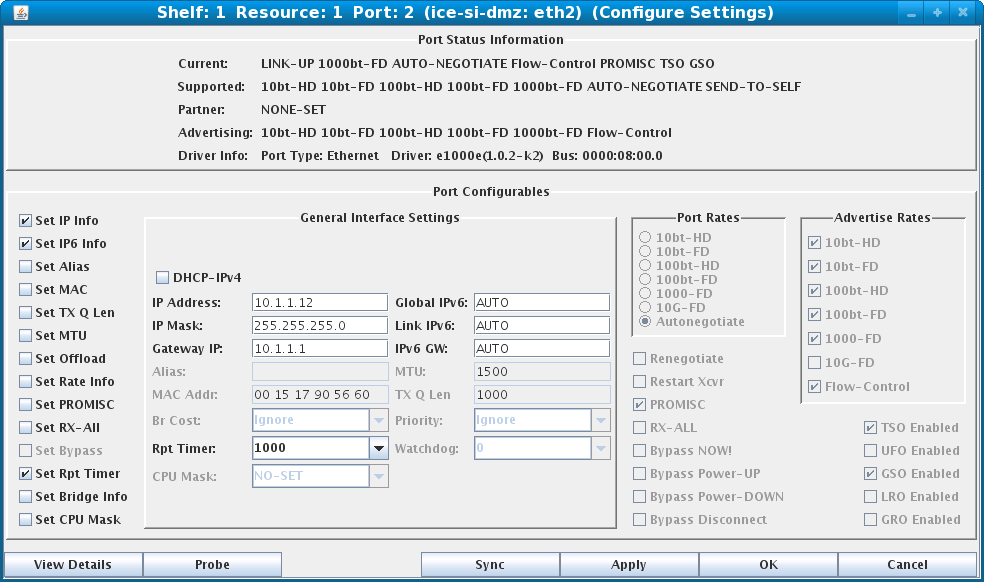
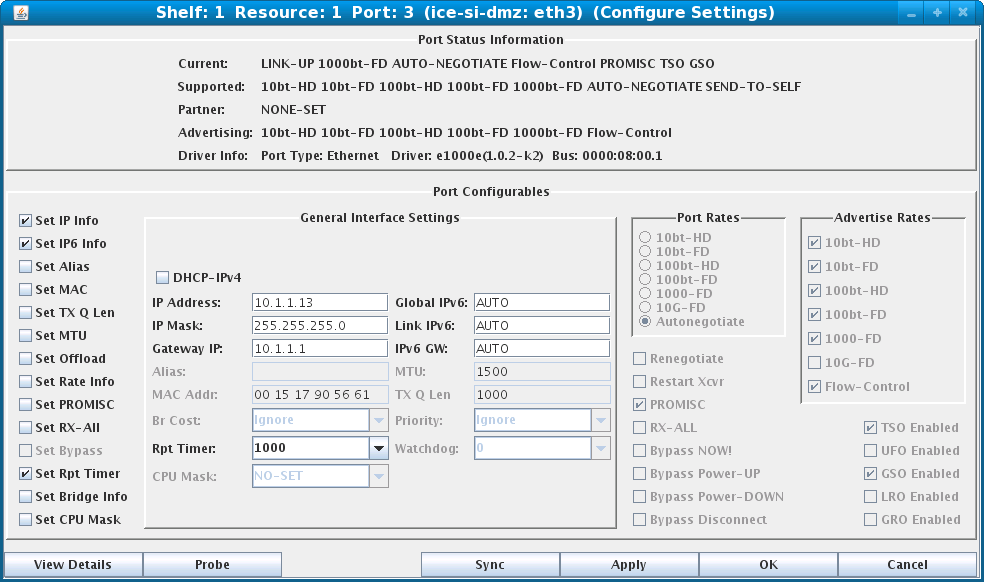
    1. On the Port Mgr tab, assign an IP address on the 10.1.1.0/24 network and a default gateway 10.1.1.1 screenshot
    2. On the Port Mgr tab, assign an IP address on the 10.1.1.0/24 network and a default gateway 10.1.1.1 screenshot
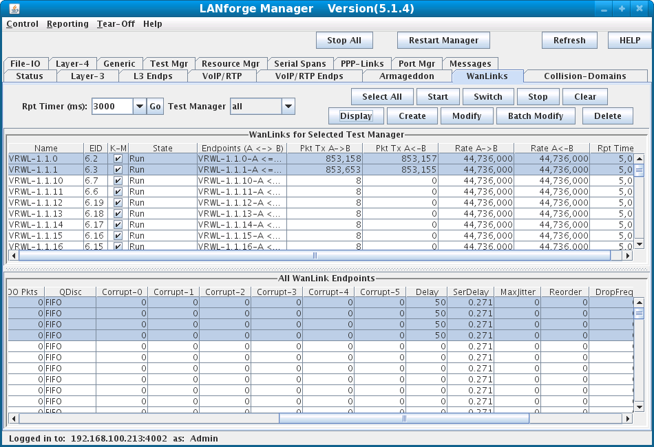
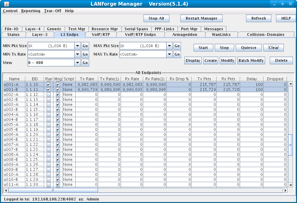
  6. The impairment settings on each WanLink will only apply to traffic that is sent or received from the switch port that it is associated with via the VLAN used with that WanLink. For example, WanLinks VRWL-1.1.0 and VRWL-1.1.1 are both set to have a total of 100ms of delay, so PC1 would see a 200ms round-trip delay when sending or receiving traffic to PC2.
    1. The total latency of WanLinks VRWL-1.1.0 and VRWL-1.1.1 is 100ms. screenshot
    2. Each end of the connection experiences 100ms of delay which gives a total round-trip delay of 200ms. screenshot

Candela  Technologies, 2417 Main Street, Suite 201, Ferndale, WA 98248, USA
www.candelatech.com | sales@candelatech.com | +1.360.380.1618
Facebook | LinkedIn | Blog